Building a Video Editing "Scrubber" (2 versions)
Lately I have been doing more video editing than I have for quite a while. I am going back through both tapes and disks that were made as long as 50 or 60 years ago (most are far younger), and digitizing them to my computer. Fortunately, most of the really old videos had already been copied to CDs or DVDs, so the quality has been maintained. But I want to ensure that I capture even these before they "age out". I have also become responsible for recording our meetings of the Prescott Computer Society, editing them, and uploading them to the club's website. The editing step is somewhat tedious, with one of the more time consuming tasks being moving to the exact frame of the video needed for clipping and joining sections. I would love to have a knob that lets me easily move the cursor to find an exact point in a video.
I think I just found a new project to pursue!
What I plan to build is a box with a large knob, which would allow me to move the editing cursor with enough resolution to easily position it exactly at the desired frame. I want to be able to "scrub" back and forth to find an exact position. As I had no idea how to accomplish some of the steps in this process, I had to research the answers to several questions before starting. Here are the questions and the answers I found by my studies:
Q: What is the best way to control the
cursor of my current video editor (Adobe Premiere Elements) from an external device? A: It appears that
other than clicking it or dragging it with the mouse, the only practical way to move
the cursor is using the
left and right arrow keys, which will move it one frame at a
time. Pressing the SHIFT key at the same time moves it 5 frames
at a time.
Q: Can I do this project using an Arduino, a Raspberry PI, or ?. A: If I can send out an un-printable character (arrow key) in the same manner as the keyboard, yes, an Arduino can do it.
Q: Can I send out codes for the arrows? A: Yes. Arduino has a keyboard emulating library which includes escape codes for the non-printing keys.
Q: Can the Arduino talk to the computer in the manner needed? A: Some models can. There are dozens of Arduino models, all with USB ports, but there are only 3 or 4 that have the required USB host driver built in. This will allow these models to talk to the computer as though they were a keyboard or mouse, without an external converter board.
Q: What is the best way to convert movement of the knob into a movement of the cursor? A: A digital encoder is the best way. There are cheap ones, and there are expensive ones. More on that later. A potentiometer could also work, but it has a limited range of travel, usually about 3/4 of a turn.
Q: Is this project even possible? A: It appears, that with the correct parts selection, this project should be successful!
Three Arduino models I considered were the Leonardo, the Due (which I have used in a couple previous projects), and the Pro Micro, all of which have the required USB configuration. The Leonardo is about credit card size, the Due is about half again longer, and the Pro Micro is about the size of 2 postage stamps. I chose the Pro Micro because of its size, the fact that I do not need a lot of inputs or outputs, and its price. I could have bought 1 for a little over $10, or 3 for $15. I chose the 3!
I decided to use one of the simple encoders I already had. These sell for less than a dollar, have contacts that rub on a patterned disk, and have 20 counts per revolution. Initially it had a detent that clicked it into each of the 20 positions, but by opening it up and slightly reforming a flat spring, I eliminated most of the detent action. Obviously I need to access more frames than 20 per revolution, so I decided to use gears to turn the encoder 4 times as fast as the knob, giving me 80 counts per turn. I could also use some tricks and generate additional signals from transitions within the normal count. (I tried this later, but the tolerances within the encoder caused intermittent problems.)
Prior to any detail design, I set up a breadboard with my encoder and a Pro Micro controller. Using only a few jumper wires I had a working model. Writing the code was not at all difficult, nor was it very large. All my research paid off! It worked, and I was able to move my video editor's cursor one frame per click of the encoder. Now I started designing and making parts!
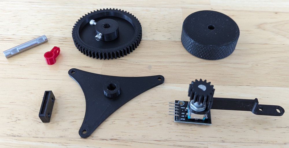
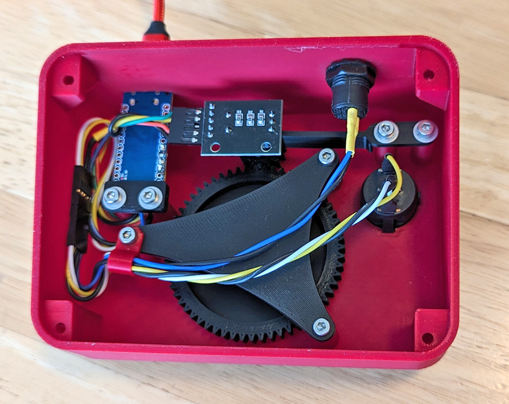
I initially printed the two gears, a 15 tooth and a 60 tooth, and the knob. The other parts on the left were built a little later in the design cycle. The 20 step
per revolution encoder is in the lower right corner, mounted on its spring mount and the gear in place.
The Pro Micro controller and a reset button are on the right. A little later I added a 3 position switch and its wiring to the controller.
Completing the design:
Now that I knew what had to go into the box, I could design it. I made a simple box and cut the bottom off at an angle (in the CAD drawing), so the top panel sloped forward at a convenient angle (a little over 14 degrees). The angle caused me some "fun" designing the bottom cover and its mounts in the case, but it all came out quite well.
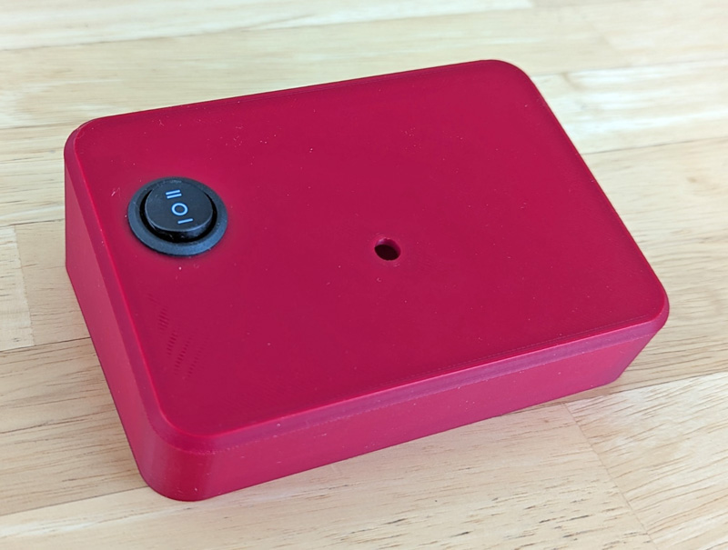
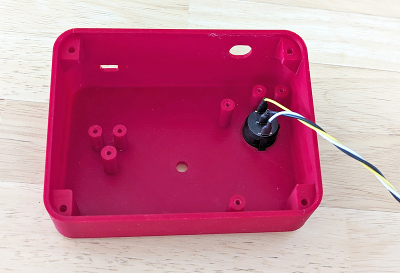
The printed case is about 1 inch high in the front and 2 inches in the rear. The bottom view shows the mounting pillars for the various parts and the 3 position switch,
which once being very tightly snapped into the hole is not going to be removed! Threaded brass inserts will be heat set into the cover mounting holes in the corners.
The bottom view shows how all the parts are mounted. The encoder is on a spring beam and is adjusted so there is
a slight pressure against the main gear. This assures there will be no backlash while turning the knob. One end of the
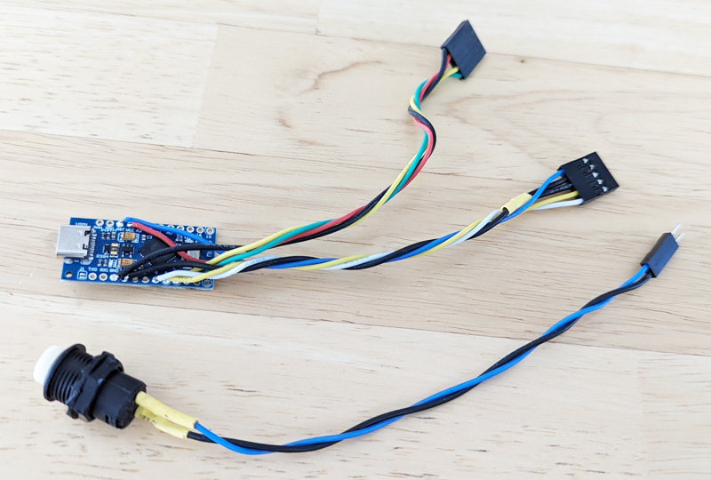
controller board has a USB C connector which extends through the back wall of the case. There is also a slot part
way through the wall which holds its circuit board. The other end of the controller fits in a slot of the retainer
which is then screwed down to a couple of pillars.
The finished box works quite well, but I really do not like the feel of turning the knob. The remaining detent is amplified by the gearing and it just turns roughly. Functionally it is fine, but I would really like more changes per revolution than the 80 I have. I did wire the 3 position switch go give me a pseudo-scaling. I can move around in the video file faster by factors of 3 and 10, but it does that by just moving that many frames per count. This prevents me from landing on a specific frame without changing the scale back to 1 and fine tuning the position.
I have also had some problems with the controller, mostly programming it. Each time you change the program, you must compile it and then download it to the Arduino. Much of the time this works flawlessly. However, some of the time I get a message that it cannot find the port to do the upload, and it just hangs there. An article I found online suggests to hold the reset button while it compiles, then release it when it tries to upload. This seems to be a satisfactory workaround most of the time, but is a bother. Also, some of the time when plugging into the USB port to start using the device, it fails to work until you press the button to reset it.
The concept has been proven and most of the technical problems have been worked out. It is serviceable, but not elegant!
Version 2:
I was looking through Amazon (surprise, surprise!) and found a "real" encoder which is affordable! It is is an optical encoder with 600 counts per revolution, and is in a fully enclosed case with a ball bearing mounted shaft. And it was only $18! I figured it would be easy to scale down the 600 counts to almost any desired value, and still always have the ability to stop on any frame, and being an optical encoder there would be no noisy signals or contact bounce, such as contacts wiping the surface of a metal disk. A minor problem with this unit is that the stated voltage range is 5 to 24 volts, which sounds fine, as the USB port supplies 5 volts. However a forum member who was talking about this encoder stated that 5 volts means 5 volts. He stated his did not work at 4.97 volts and my port measured less than that. I bought it anyway. I also found that mine would not work with the USB supplied voltage. I supplied it 12 volts and it works great! Adding a boost converter to the parts list will solve this problem. A boost converter takes a DC voltage and through the magic of electronics, raises the output voltage to any value up to about 30 volts. I figure that 12 volts should leave good margins from each end of the 5 to 24 volt range.
A design using this encoder would have the knob directly on the encoder shaft, eliminating any gears, which should be much simpler, but there was another problem: I was interested in keeping the basic design of my first case, but the length of the encoder would not allow it to fit without some manipulations. I actually considered two options to overcome this:
- Mount the encoder on the top panel and extend the bottom of the case to accommodate it.
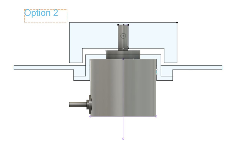
- Extend the encoder through the top panel and hollow out the bottom of the knob to accommodate it.
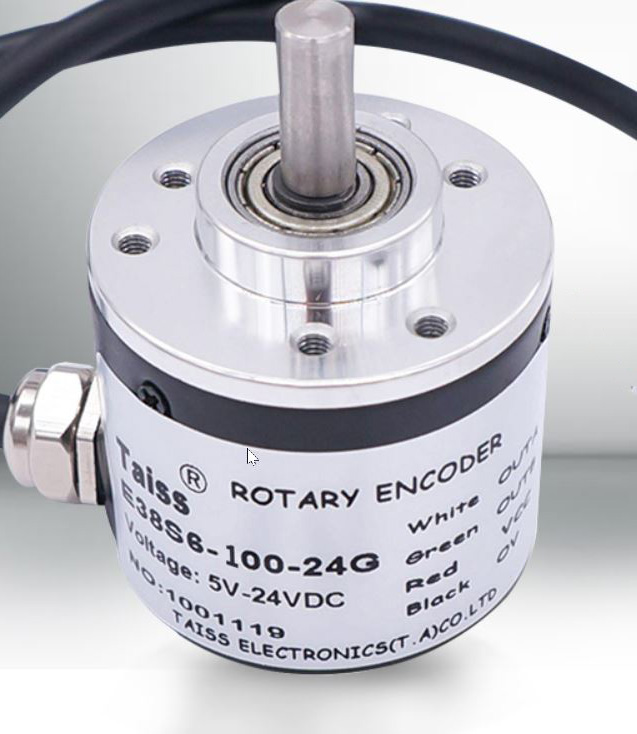
The left shows the optical encoder, a well built, nearly friction free, totally enclosed unit which produces 600 steps per revolution..
The right is the construction of the encoder mount. A hat shaped part, which mounts the encoder, protrudes through the top panel. The
edge of the panel hole is made thicker to adequately hold the mounting screws, and the bottom of the knob is relieved to provide clearance.
Moving the encoder slightly toward the rear of the panel, to a thicker part of the case allowed sufficient clearance from the bottom cover.
Once the encoder mount was complete, the other parts fit nicely pretty much like they did in version 1. The primary difference was providing a small pocket area to place the boost converter. I used hot glue to secure this.
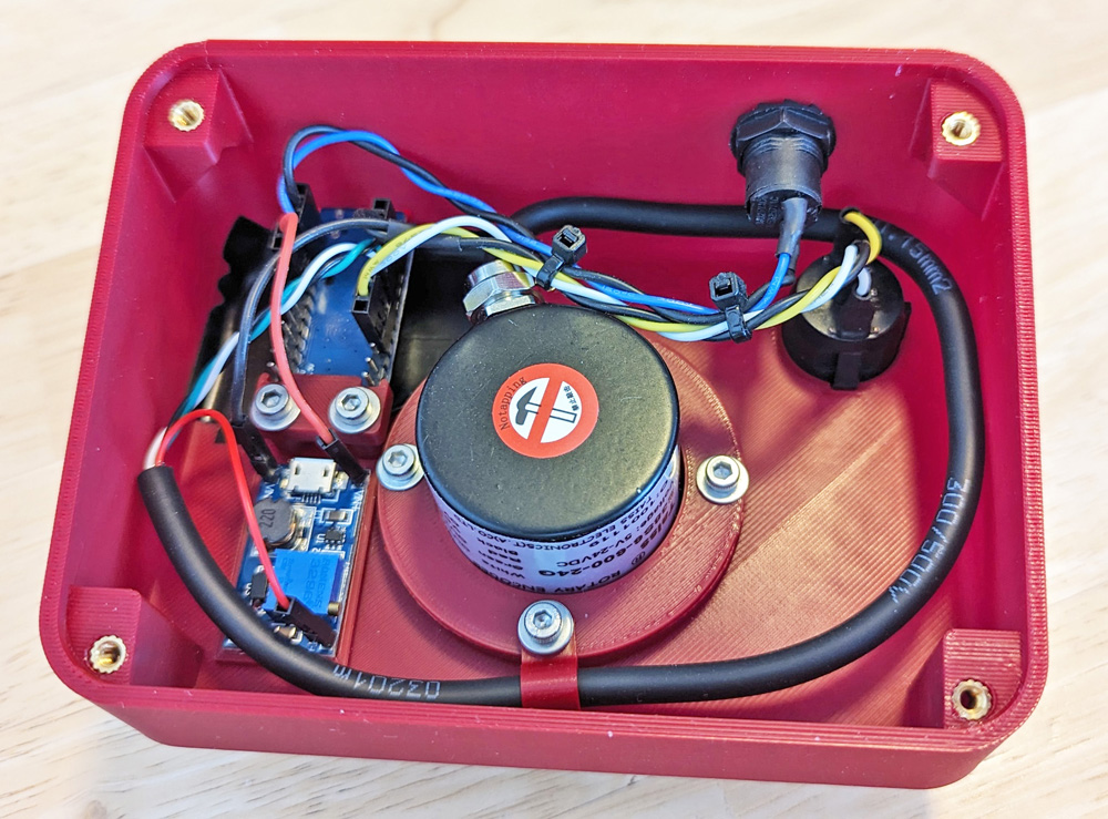
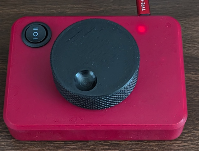
All the contents fit easily in the case. I lined the inside of the case with black electrical tape in the area of the controller, as three bright red LEDs on the Arduino showed right through
the red case. I actually turned that to my favor by cutting a small round hole in the tape directly over the Power-on LED, giving me a small pilot light showing through the case.
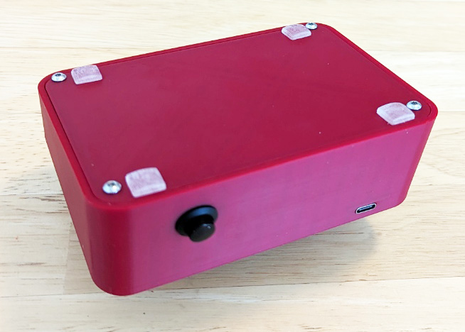
The right picture shows the bottom cover in place. It also shows the reset button and USB C port on the rear of the case.
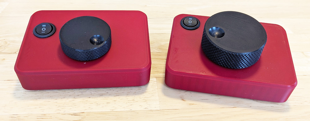
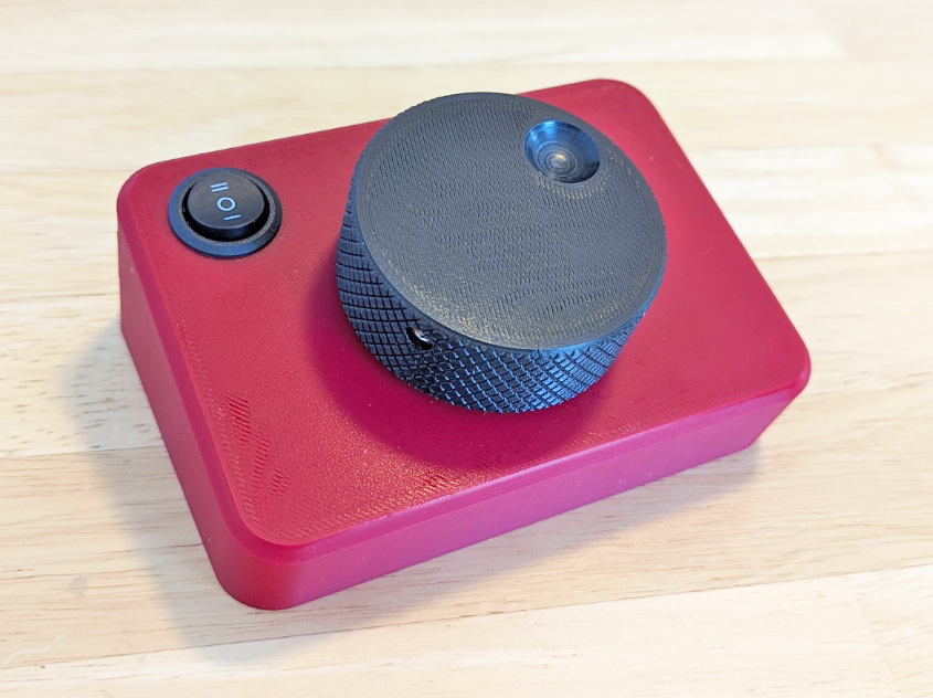
These are the two completed units. Version 1 is on the left, version 2, the right. The primary visible difference is the larger knob
on the later version. In use, version 2 is much smoother and easier to use.
Final Conclusions:
I am much happier with version 2. Initially, the knob turned too freely. It was easy to disturb it by a few frames as you let go. A felt washer between the knob and the end of the encoder provided just enough friction to overcome this tendency. The action is still very smooth. The 3 ranges of 100, 200, and 600 counts per revolution are quite usable, with 200 being about optimal. The 600 range allows more rapid moves, but can easily out pace the editor's capability to receive the rapid pulses. It doesn't lose them, it just stores them and keeps moving after the knob stops, until all the steps are applied. I found this was a nuisance in actual use, so I added a delay in the step routine to slow it down to about the same speed as the editor.
This was a short, fairly straight forward project, but it did require some study beforehand to determine what techniques would work. It has been a while since I programmed an Arduino and it took a little time to reacquaint myself with the C++ programming language subset that is used.
All in all, a good outcome!
GO BACK
R. S. Mason March 2024