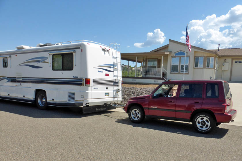
Replacing my Jeep tow car with a 1996 Geo Tracker
Ever since I bought my Chevy Volt, I have not wanted to drive anything
else! As a result, except for towing it behind the motorhome to
use on trips, I have driven the Jeep very little. For the year I
have had the Volt, I only put 1100 miles on the Jeep (Almost a quarter
of those miles was added driving down to Gilbert and back to pick up my
Tracker.) Obviously I
should sell it and recoup its current value, but then what do I do on
motorhome trips?
My solution was to buy a 1996 Chevy Geo Tracker and sell the Jeep.
Finding a new tow car
I was interested in finding a light weight, 4 wheel drive vehicle
which
can be towed 4 wheels down behind another vehicle. The best
candidate I found was a line of cars which started with the Suzuki (a
subsidiary of Isuzu) Sidekick, which then became the
Tracker.
General Motors owned the Geo name, under Chevrolet to give them a way
to sell their customers small foreign cars. They went into a
joint venture with Isuzu to make the Tracker line and put it under
their
Geo name, then in 1998, they dropped the name Geo and sold
a Chevy Tracker. Suzuki continued the line with the Vitara and
Grand Vitara.
For several months I have been causally looking on Craigslist to see
what is available and for how much. I was mostly finding Geo
Trackers in the 1990's, and for prices ranging from $1500 to about
$5000 depending on condition, age, and equipment. Finally in
August 2017 I decided to get serious, and after a number of calls
decided to look at a 4 door model in Gilbert, about 130 miles from
home and near the middle of the price range. I looked at it and drove it and it passed muster. I
then towed it home behind the Jeep on a U-haul tow dolly to start my adventures with it.
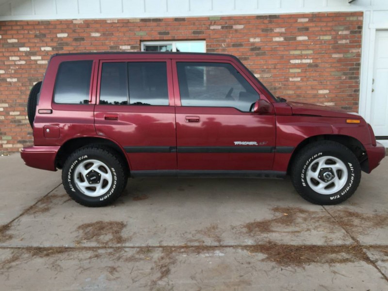
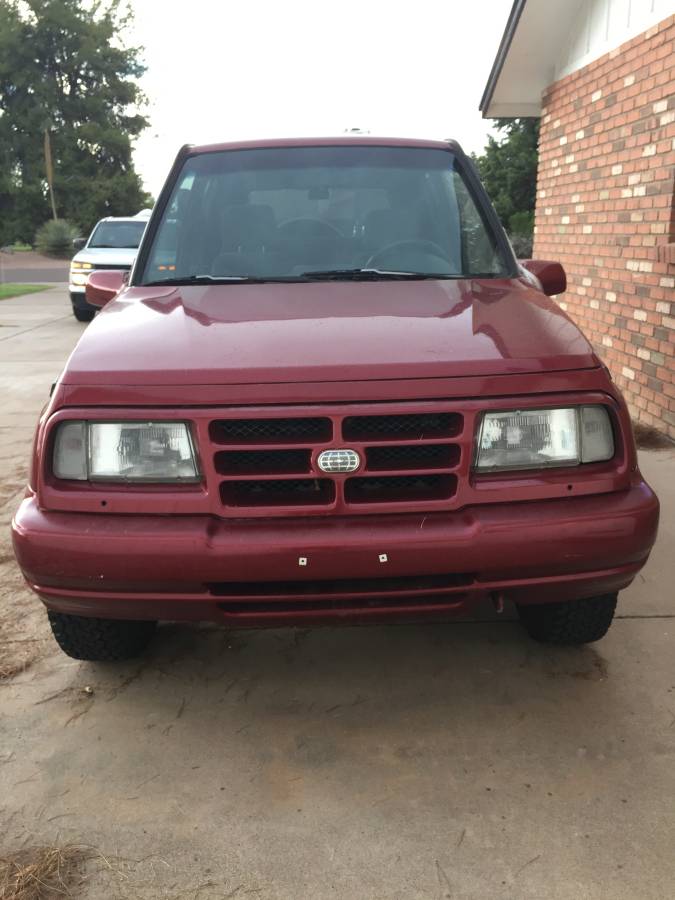
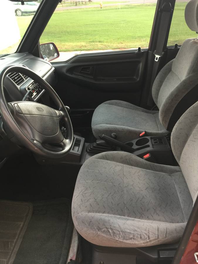
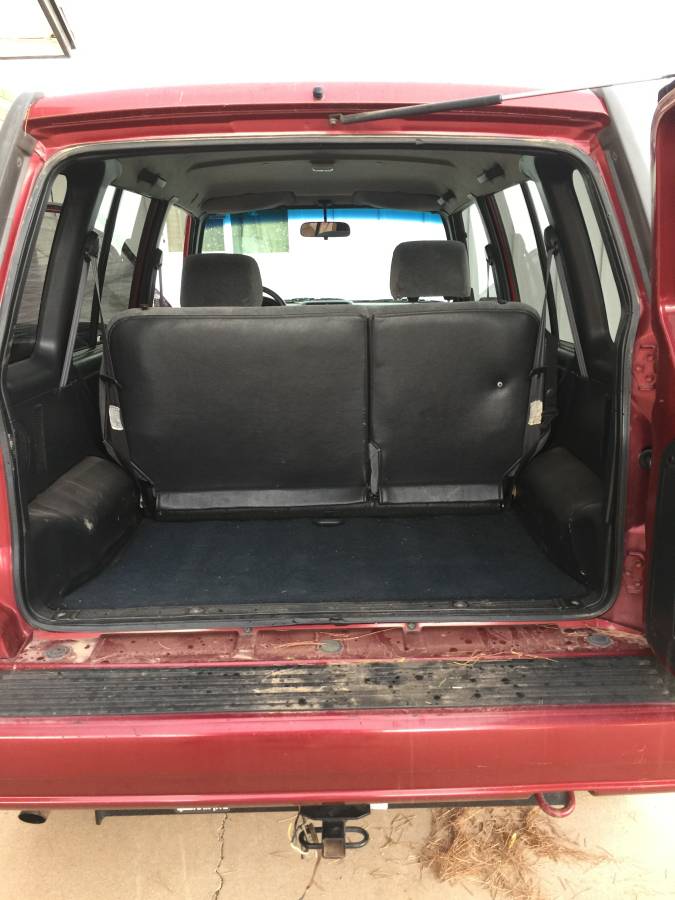
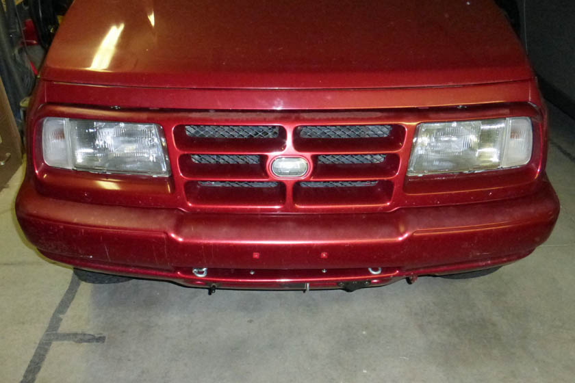
It is really quite a nice car. Most of the Trackers listed (and
seen around town) are the 2 door convertible. These have a roof
over the front seat, and a convertible top over the rear. There
are hard tops available. What I bought is a fully enclosed 4 door
which looks eerily like my Jeep, even down to the color. It is
just quite a bit smaller. It is also a full ton lighter with a
curb weight of about 2400 pounds vs. the Jeep's 4400! It is a
full 4 wheel drive vehicle with the transfer box shifter capable of
2WD, 4WD low, 4WD high, and neutral. The main transmission is
a 5 speed manual. There are manual hubs on the front wheels with
a free wheeling position and a lock, where the wheel is attached to the
front axle shaft. The engine is a 16 valve overhead cam 1.6
liter, 95 HP engine. The car has power door locks and power
windows. It doesn't appear to have a receiver for a remote fob -
and none came with the car.
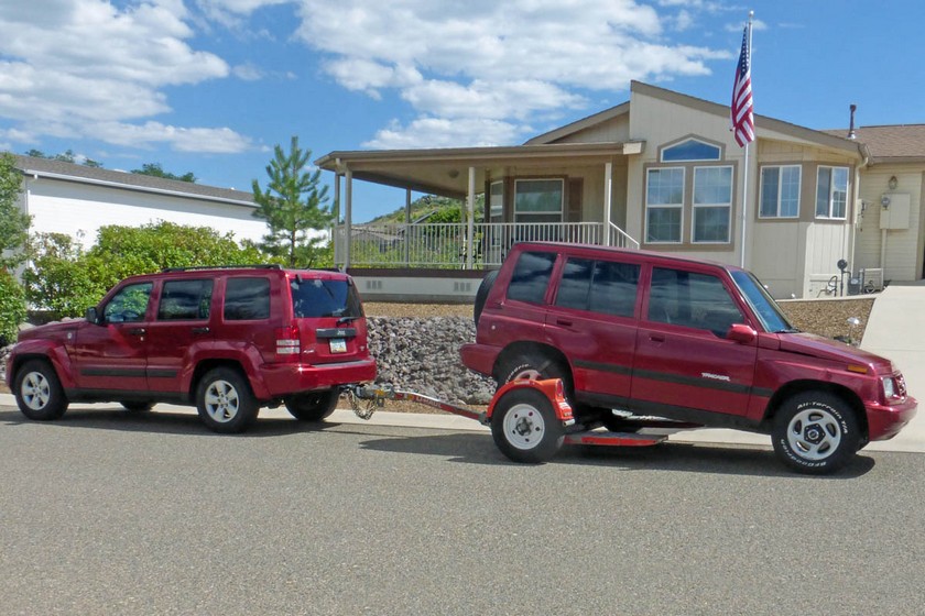
I
have just arrived home after towing the Tracker 130 miles behind my
Jeep (It was a long day!) This reverse towing is the method
the owner's manual says is the only way you can tow it on a
dolly. You must tow it rear wheels up and the front hubs
unlocked. The problem
I discovered with this method (heavy end at the back) is that at about 55 miles per hour it
becomes very unstable, starting to swing side to side.
I drove
the 130 miles home at 52 miles per hour on cruise control. I had to be
very careful on downgrades to not let the speed increase.
If I
were to ever try this again, I would tow front wheels up and disconnect
and tie up the rear drive shaft. It should be very stable that
way.
The other option would be a full car trailer, all wheels on the trailer.
The following 6 pictures were taken by the seller and posted on her
Craigslist ad. (They were quite good, so I did not re-take them)
The Jeep is sold
After I did enough work and inspection of the Tracker to be totally
confident it would meet all my needs, I listed the Jeep on Craigslist,
and a few hours later, sold it to the first prospective buyer for my full asking
price. It was a beautiful car and had very low mileage for a 6
year old car. He got a good one! Before I was ready to list
it, I looked up the Blue Book value of my Jeep and discovered it was
quite a bit higher than I had thought. I ended up selling it for
a higher price than I first thought and the difference paid for about
3/4 of the Tracker. I was also able to deposit a 5 figure check to my investment account.
Getting the Tracker in shape
There were several problems with the Tracker which required repair, and
I need to install all the appliances for towing behind my
motorhome. There were really only two major problems, along with
several more nit-pickers.
Important things to fix:
The
driver's side window glass was loose and would twist forward out of its
guides and jam when closing the window (unless you hand guided it).
The headlight low beams were non-functional
The power window works by a trolley with a rigid cross
piece being moved up and down. The glass in the window is
fastened to this cross bar with two molded plastic clips, which are
glued to the bottom of
the glass and bolted to the trolley. The rear clip was broken,
allowing the glass to rotate about the bolt of the front one.
Rather
than trying to totally remove the glass and find a new clip, I made a
couple aluminum pieces which glued to the window on each side of the
glass straddling the original clip. These pieces then bolted to
the
trolley in place of the broken clip. It worked like a charm and
should
be much stronger than the plastic clip.
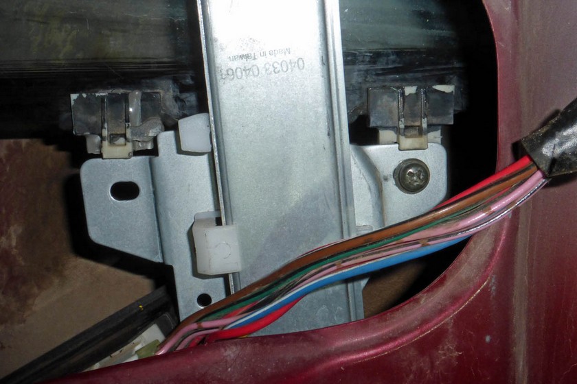
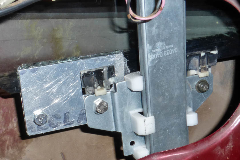
This is the window trolley. The left clip is broken and allowed
the window to pivot about the right clip's screw. On the right is
my fix. The plates are
larger than necessary, but I wanted to make sure it held. So far, it works great!
The headlights were a bigger problem to diagnose and an easier one to
fix than I had figured. The bulbs checked out as OK and the high
beams and
all the running lights worked. Just probing the wires in the area
got me nowhere. The factory service manual I had
ordered from Ebay was not here yet, but I managed to find some
schematics online that showed how the Tracker uses daytime running
lights
(DRL's). The common theme of the several articles I found about
the
DRL's was to look for the module under the dash with the connector
burned on one end. Sure enough, mine was badly burned and melted
on
one end. The easy solution was to clip the headlight wires (the
burned
ones) and connect them together, bypassing the DRL module
entirely. After doing this, all the lights
work
great; I just do not have DRL's. I have opened the DRL module and
can reproduce it without too much problem, but with the chronic
problems of the original, I probably won't.
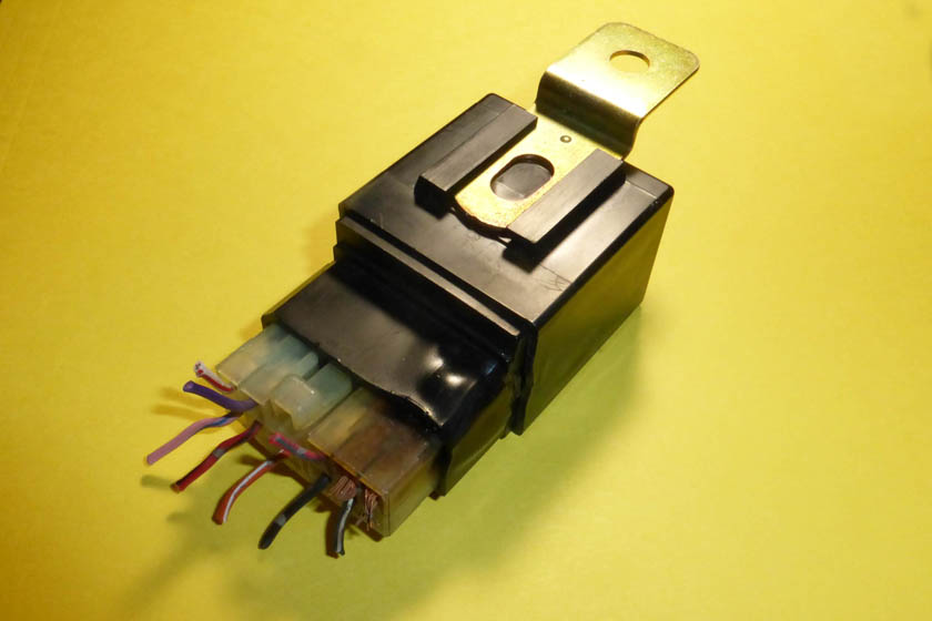
The DRL module had a burned and melted area on and around one end of the connector. This was
a common problem and obviously a design error.
The nit-pickers:
Windshield wiper blades were shot
The spare tire was flat
I was given only one key
The hood latch cable was not mounted and just flopping loose
The dome light lens had a broken tab and had been glued in
The spare tire mounting studs were stripped or deformed
The cruise control didn't release when pressing the clutch
The first 4 items are total non-brainers. I bought new wiper
blades; I inflated the spare and it held its pressure; I had extra keys
made. The hood release was a strange one. The cable with
its T handle was flopping loose in the glove compartment. I got
down low and looked above the opening and saw a bracket mounted at a
strange angle. The cable mounting fit and I fastened it with screws
that were loose in the bracket. If you didn't know, you would
never find the hood release. To open the hood, you open the glove
compartment and reach in to the right, above the opening feeling for the T handle.
You pull it and the hood pops open.
I initially came up with several schemes for repairing the dome light
lens, but ended up buying a like new complete assembly from Ebay.
I also bought a couple LED light bulb assemblies to replace the
dull-orange-glow original incandescent. It's nice and bright now!
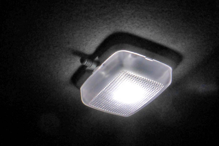
The used dome light is like new! With the LED light, the output is much whiter
than the orange color of the original, and the light output is much greater.
There were only 2 mismatched nuts holding the spare tire to the bracket
on the rear door. The third stud was stripped to the point that a
nut would not gain any grip. The other 2 studs had deformed and
stripped threads, but would still engage the nuts. I ordered several
high strength metric bolts of the correct size and length from Ebay,
along with some decent looking lug nuts. I then removed the
bracket from the door and milled the heads of the studs flat to the
back of the bracket where they had been welded, and knocked the studs
out. Once my bolts arrived I put them through the holes
and welded the heads to the back like the original. I now
have pristine threads, and with the very high strength steel, hopefully
the threads will remain good even with the spare being dragged over the
threads as it is put on and off.
The threads on the spare tire mount were really in bad shape. One
of the studs wouldn't even hold a nut on, you could just pull it off.
The other two still tighten OK, but were
beat up and worn. The new studs I just installed look much
better, and should hold just fine. A little paint didn't hurt
either.
The final item, the non-working clutch switch turned out to be caused by the fact that there was no
connector plugged into the back of the switch. I found the
connector hanging by its wires nearby. Someone had stripped the
insulation of each of the 2 wires to apparently try connecting to them
- I have no idea why! I taped up the insulation and found why it
was not plugged in. It seemed like it took me forever to
correctly position the connector up high under the dash, among several
large wire harnesses. I finally got it lined up and was able to
press it into place with the tips of my fingers. The cruise control now
disengages correctly if the clutch if pressed. (It already worked
when pressing the brake pedal.)
Now for the towing mods!
The largest task on the new Tracker is to outfit it so it can be safely
towed behind my motorhome. That really is the major assignment
for this car - to be a toad! (Some people would call it a towed.)
There are three major items that need to be added to the car for this
to happen:
1. I need to install a baseplate, which is the structural
equipment which attaches securely to the frame of the vehicle and
allows a tow bar to be attached.
2. The lights need to be modified so that the motorhome circuits will power them.
3. The braking system which I have previously had
installed on my Subaru and then my Jeep needs to be installed on this
car.
Installing the baseplate
Each manufacturer of tow bars and associated equipment makes their own,
usually unique, combination of the tow bar and the baseplate. The
tow bar is generic in that the same bar can be used for almost all
cars. There are usually several different models, but each is
universal. The baseplate, on the other hand, is custom designed
for a specific year, model, and brand of car, or series of similar
cars. Since I have owned the Foretravel I have always used the
Roadmaster brand of tow bars. I had one for many years, and then
upgraded it to a newer model several years ago. Since I stayed
with Roadmaster, I didn't have to change anything but the tow
bar. I have had Roadmaster baseplates on my Saturn, Honda CRV,
Subaru, and my Jeep. Now I need one for my Tracker.
Roadmaster makes different levels of baseplates as well as tow
bars. Some have permanent brackets protruding out the front of
the car, others have removable bars. For the 4 door Tracker, they
only offer one type, and that is the one that has removable brackets,
which when removed make it hard to tell that there has been anything
done to the car.
Four days after ordering it, UPS brought a very heavy box to my porch,
and even offered to carry it into the house (I foolishly
refused). Once I got the box open, I could easily handle the
individual parts. To install it you must remove the grill and the
plastic bumper cover. At one point you must also remove the
bumper itself to get enough clearance to drill a hole in each side of
the frame.
This baseplate really only has 2 pieces on each side. The largest
one bolts to 4 existing holes in the front frame cross member and to 2
holes you must drill in the bottom of the bumper. Then there is a
brace which attaches to the same two bumper holes and extends back
alongside the side frame where it is bolted. It sounds easy, but
there are several "gotchas".
After removing the bumper cover and the grill, you have access to
install the baseplate. The main pieces attach through the front
frame member with 1/2 inch bolts. It looks easy, but the bolts
thread into a long nut-plate that has to be put into the frame through]
one of the holes that barely show in this picture on the bottom.
The plate then must be maneuvered into position and the bolts
threaded into it.
Then, using the holes on the brackets for location, you drill 4 holes
total into the bottom of the bumper - not hard. THEN you must
insert a backing plate through the holes you can see in the front of
the bumper, and align the square holes in it with the drilled holes
in the bumper. THEN you somehow insert 1/2 inch carriage bolts through the same bumper holes and work them through the
square holes in the backing plate and the drilled holes in the
bumper. I managed all the above using bent pieces of wire, needle
nose pliers, probes, a lot of patience, and a lot of luck!
The last assembly step is to mount the two angle plates, mark a hole
location from the bracket to the frame, remove the bumper, being
VERY CAREFUL to not disturb the carriage bolts in the bumper. Now you can drill the frame holes and re-assemble it all.
I didn't disturb a single carriage bolt! As the very last step, I
went back bolt by bolt and made sure the washer and lock washer setup
was correct, added some red Loctite to the threads, and using a torque wrench, tightened them to the correct tightness.
Before putting the front end back
together, I had to decide how to mount the electrical connector, the
air fitting for the braking system, and the break-away switch.
The logical place is on one of the ledges of the bumper cover in one of the
two air inlets. As the plastic bumper cover is not very rigid, I
made a 1/4 inch thick aluminum plate to attach to the bumper cover and
mount all the accessories.
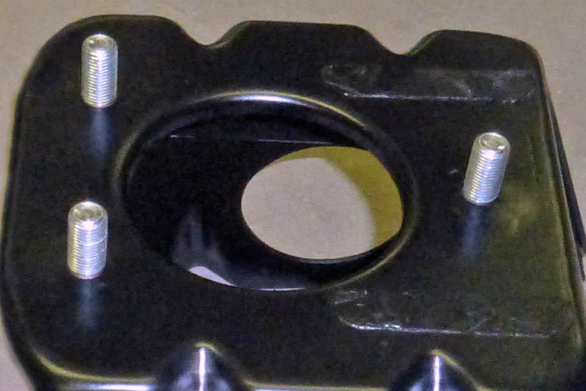
This 1/4 inch aluminum plate has tapped holes for mounting the electrical connector bracket, the
break-away switch, and the braking system air connector. It also has tapped holes for mounting
to the bumper cover.
Here the plate is mounted to the bumper cover, shown upside down for visibility. The accessories will
hang down from this plate. It is mounted on spacers to allow the screws to protrude through the plate slightly.
The bumper looks awful from this angle where driving over brush and other obstacles has left scars that really
show. When mounted right side up, this is all very low and hardly shows.
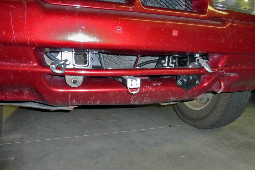
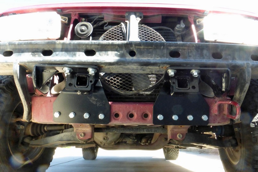
With all the equipment installed and the grill and bumper cover
replaced you can see all the accessories. In the lower vent are
the brake system air fitting, the break-away switch, and
the electrical connector. In the upper vent the links allow easy
connection of the safety cables which stay on the tow bar. Next
to them is the receptacle for inserting the mounting
bars. From a more normal height of view, the right hand picture shows how unobtrusive the fittings are.
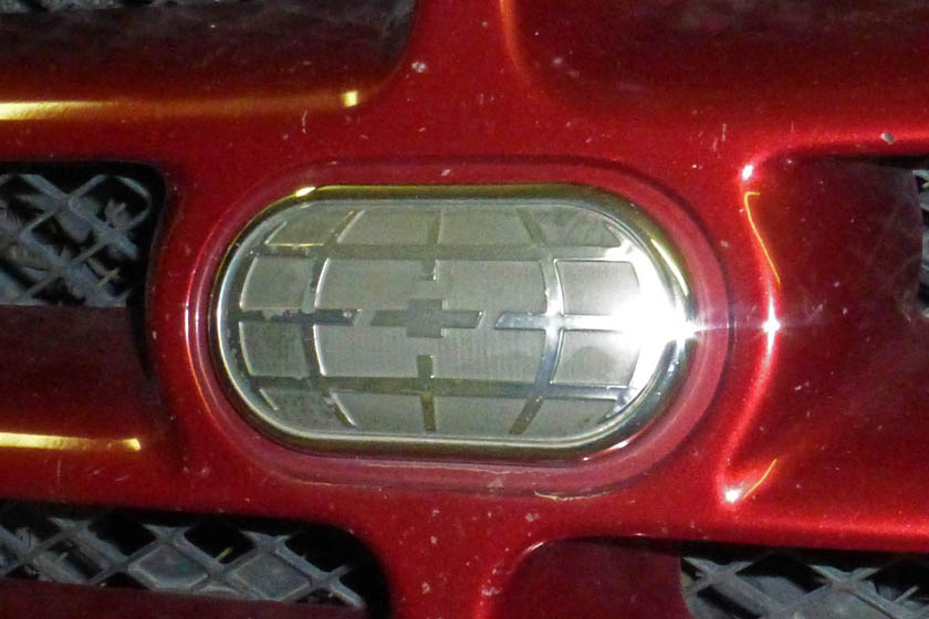
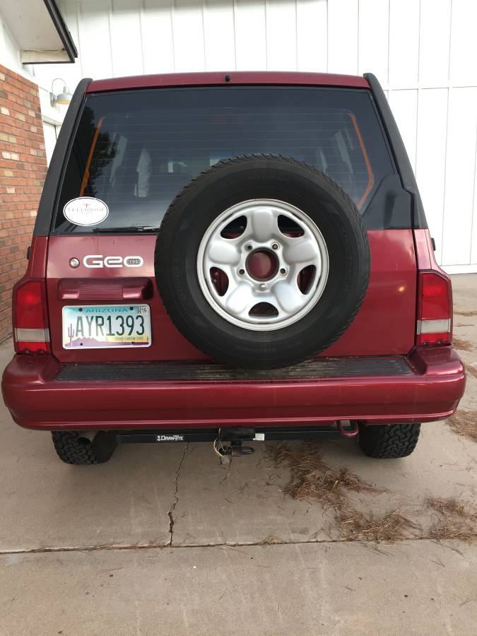
As a point of interest, one of the Internet forums on Trackers had a post stating that the Geo
emblem had been modified when Chevy took it over, adding the trademark bowtie to the center.
Sure enough, there it is!
Updating the wiring for towing
I have wired a number of cars to be towed. The objective is to
connect the stop lights and the tail lights in a manner that either the
motorhome or the vehicle itself will correctly operate the lights and
not cause any unwanted interference. For instance, you want the
tow car tail lights to come on when the motorhome lights are on, but
you do not want the tow car to try and light all the lights on the
motorhome if you should turn on its lights while connected. With
all the computers in modern cars, you also never want an outside source
to be able to feed back into a computer, many of which monitor the
lighting. The most common way to accomplish this is to feed the
power from the motorhome and the power from the towed car to the light
bulb through a diode on each line. A diode is like a one way
valve. The power can get from one line to the light bulb through
its diode, but the diode on the other line prevents any power from
going back into it.
Even though most cars nowadays have separate bulbs for the stop lights
and the turn signals, the common practice for trailer towing is to
combine both these functions and use the brake light for both.
This is handled in the towing vehicle which then only needs to run
wires for the right stop, the left stop, and the running lights to the
trailer or towed car, along with a ground wire.
My Tracker came with a trailer hitch setup (a small 1 1/4 inch
receiver) and a somewhat very kludgey wiring job. I tore all their
trailer wiring out and decided to redo it at the same time I do the tow
wiring, as it is in the same area and deals with some of the same
wires. I worked up a master diagram of all the changes and
realized that I need a total of 9 diodes! I need 2 on each stop
light as describe above, I also need two for each line going to the
trailer connector to convert the separate turn and stop lights into
common lines. This brings the total to 8. I also need a
diode to make sure the Tracker can never back feed the running lights
into the motorhome. Its many running lights are sure to blow the
Tracker's fuse. I decided to use Schottky diodes as the voltage
drop through them is less than half that through conventional
diodes. These diodes have become more plentiful and affordable
lately because of their wide use in solar panels to prevent back
feeding of power from one panel to another.
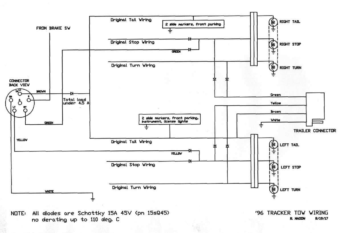
This is the diagram for connecting the lights for motorhome towing and
for the Tracker towing a trailer. For the running lights, I
usually just power the rear
tail lights, however the Tracker has 2 marker lights on each side I
also want to light. It was much easier to just power the entire
string of running lights, so
in addition to the lights I really want, I am also powering the front parking lights and the instrument panel lights.
To install the wiring I first needed to run wires for the left and
right turn/stop lights. At the same time I ran a video cable and
a couple power wires for my future backup camera. These wires all
ran from the right rear tail light housing, under the car, along
the right side frame member and up to the engine compartment where the
backup camera wiring went through the firewall to behind the glove
compartment and the others to the front of the car where the towing
electrical connector is. All the wiring changes for the stop and
turn wiring were made in the fender openings exposed by removing the
tail light assemblies. The running light wiring consisted of
tapping into the wiring behind the left front parking light and
connecting it to the front connector through a diode. The last
wire I needed to run was a link from the Tracker brake pedal switch to
the towing connector. This will light a small lamp on the
motorhome dash when the Tracker brake pedal is depressed. This is
a verification that the braking system is working correctly.
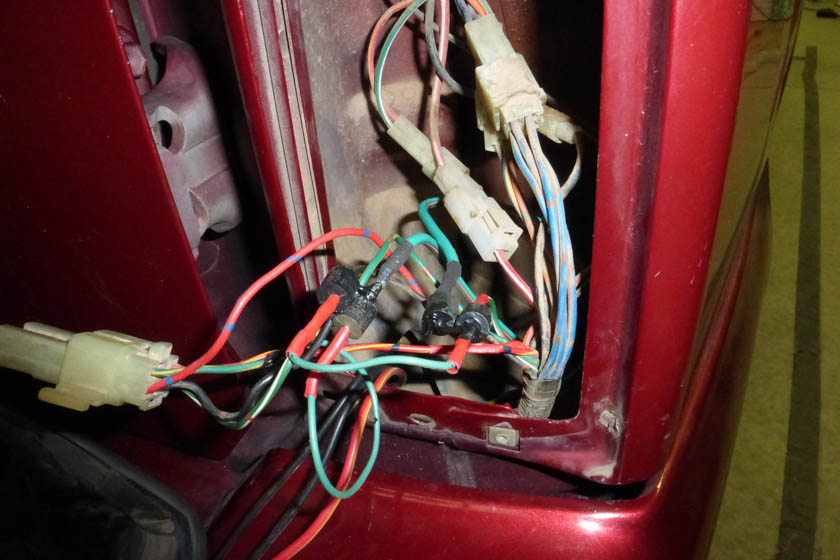
The left picture shows the connections for the right turn/stop
lights. There are 4 diodes in place for both the car-being-towed
function and the car-does-the-towing trailer light
functions. The wiring for the left light was similar, except it dosn't have
the extra 3 wires shown dropping down over the bumper. These are
the backup camera wires which were then run
up to the grommet the factory used to run the wiring harness into the
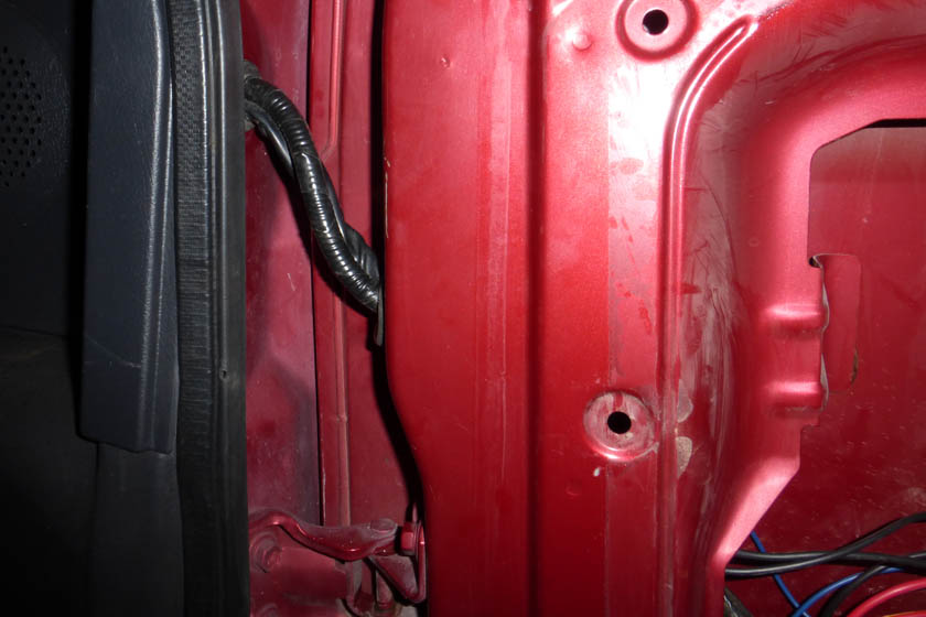
rear door. The right picture shows that I have run the backup
camera wires alongside the original wiring.
These 2 harnesses flex and twist slightly as the door opens and closes.
The left picture shows why I decided to replace the trailer wiring. The right one is how it ended up.
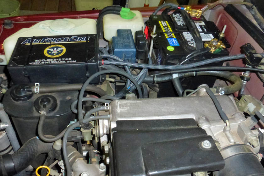
Tow brake system installation
Prior to selling the Jeep, I made sure to remove all parts of the SMI
Corp. Air Force One braking system from the Jeep. This consisted
of a control box, an air connector on the front bumper, an air cylinder
connected to the brake pedal, the front bumper break-away switch and
various wires and hoses.
I really searched hard for a good place to mount the control box.
I finally decided that directly over the cruise control servo was the
best location, and after testing with some small paper strips taped
into loops and closing the hood, I also decided that it would clear the
closed hood (barely), I mounted the control unit with zip ties
and connected and plumbed it as I have on my 2 previous tow cars.
Those details are shown here.
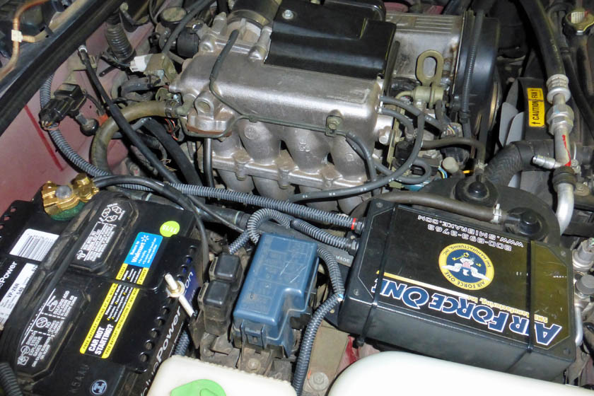
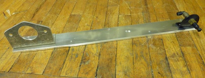
The control module for the brakes fits very nicely in a small depression directly on top of the cruise control servo module.
It is held in with zip ties and is in a good position to connect all the wires and hoses.
There are electrical connections from the control box to the break-away switch and to fused power from the battery. There
are two high pressure air connections using 1/4 inch hard plastic air brake hose, one from the front bumper air connector, and
the other to the air cylinder on the brake pedal. These are all
enclosed in split loom for protection. The other hose is a large
diameter vacuum hose shown curving around from the rear port on the engine, through a check valve, a tee, another check
valve, and then into the control box. The hose off the tee goes
to the vacuum booster on the brake master cylinder. The control
box always maintains a vacuum on the booster so the brakes always have the advantage of the stock power brakes while
being towed. There is a provision that if the break-away switch
is activated (a plunger attached to the motorhome is pulled out)
the brakes on the car will be activated and stay on to stop the car in case of a catastrophic disconnect.
The cylinder mounts on the brake pedal, and through a small aircraft cable attached to the floor, pulls the pedal when activated
Proof of the pudding
Now that all the systems have been installed, and tested as well as they could be, piece by piece, it's time to really test it.
I pulled the motorhome out as though I was leaving on a trip.
I
had already installed the removable tow arms and cross member for the
tow bar attachment on the Tracker. I pulled the car behind the
motorhome and connected everything for travel. I made sure the
front hubs were unlocked, the transfer case was in neutral, the
transmission was in 2nd, and the parking brake was released (all per
the owner's manual). I put in the
key turned to accessory to unlock the steering wheel. I then
checked out all the lights to make sure they all worked and that the
correct ones were activated. All was good. I then drove a
few miles on our local streets. Everything worked as it was
supposed to. The dash
brake check light came on whenever I applied the brakes and the car
tracked well. It is a Tracker after all! When I got home, I
pulled the break-away plunger
and the brake pedal was pulled down with quite a lot of force. I
was
able to pull it against the cylinder, but it was hard.
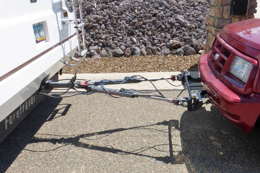
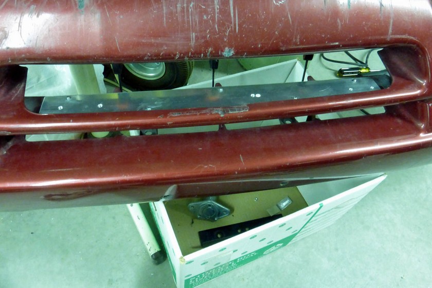
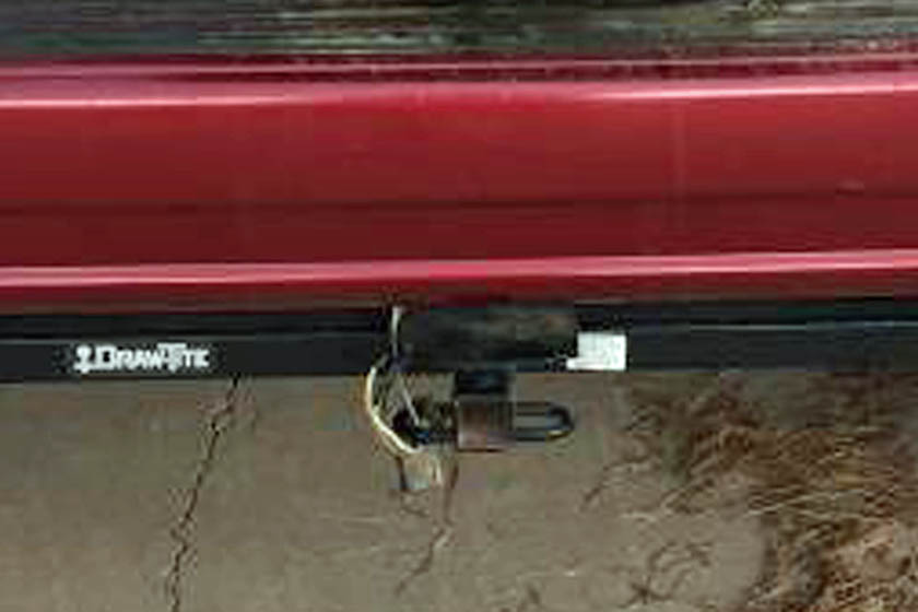
This shows the car connected with all the wires, cables, and hoses. It is ready to tow.
The removable bars are inserted into the baseplate, and the cross bar is connected to them. The tow bar connects to this
cross bar. The safety cables are connected to the loop links, the brake system air hose is connected to it's connector,
and the electrical cord is connected. The very light weight curly cord connects to the break-away switch.
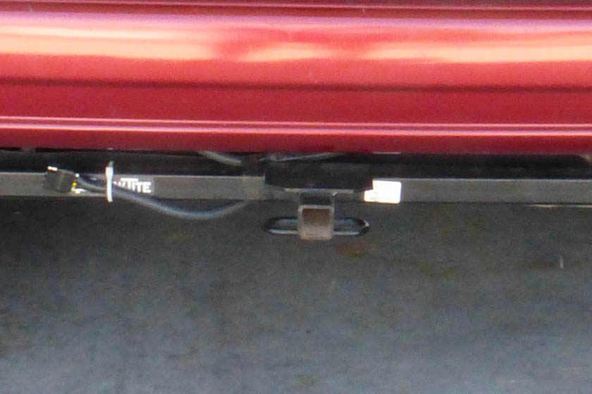
And here we are, ready to pull away. The tow bar in this setup is the closest to being level of any towing setup I have
previously had. That's a good thing!
Success! I'm now ready for my first real trip with it.
However, there is one more thing I wanted to do:
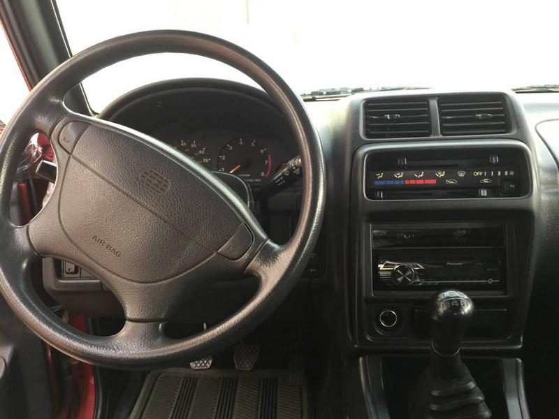
Installation of new radio
The seller had replaced the radio a few months before I bought
it, but the unit she chose just bugged me! Car radios are usually
available in 2 standard sizes: Single DIN is 2 inches high by about 7
wide, a Double DIN unit is 4 inches high and about 7 wide. This
car came from the factory with a Double DIN sized radio, which she
exchanged for a Single DIN unit - a Pioneer $60 Walmart special.
I wanted a Double DIN touch screen 6+ inch display screen! It's
just sacrilege to install a small radio in a large hole!
I did quite a lot of searching on-line for radios and found so many I
had a hard time absorbing it all! I finally decided to enumerate
the features I really wanted, such as a REAL volume control knob, front
panel (not back panel as so many have) USB and 3.5mm inputs, and
several others. After I narrowed my search down to only those
radios that met all my requirements, I still had a lot to choose
from. In the end, I decided on one Amazon was carrying for under
$150, and it included GPS navigation! That wasn't even on my
list. This was a very cheap radio for its features - I saw others
ranging from several hundred to about $1000. For this
application, cheap is fine.
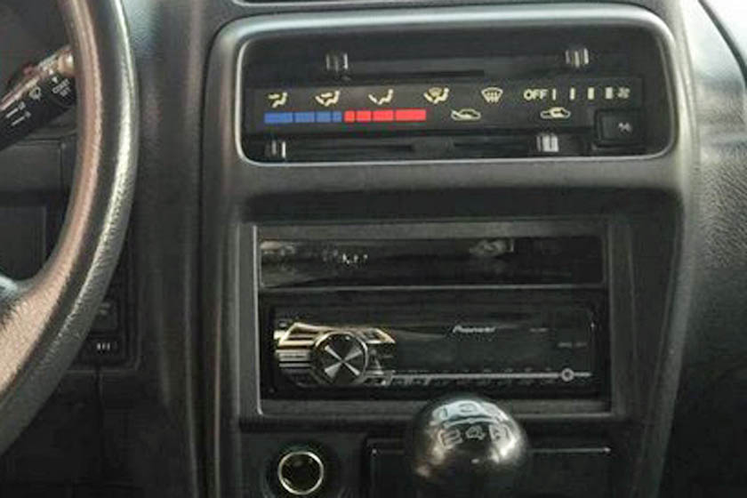
The left picture shows the radio that was installed in the car
when I bought it. There is nothing wrong with it and it works OK,
but I just don't like it. Above the radio, the installation
kit supplied a small cubby hole to store CDs etc. On the right is
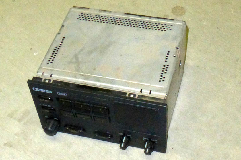
the factory radio. She had it in the back of the car, and said
she would throw it away for me. I said "no" and
took it. As it turned out, I'm very glad I did! (see below)
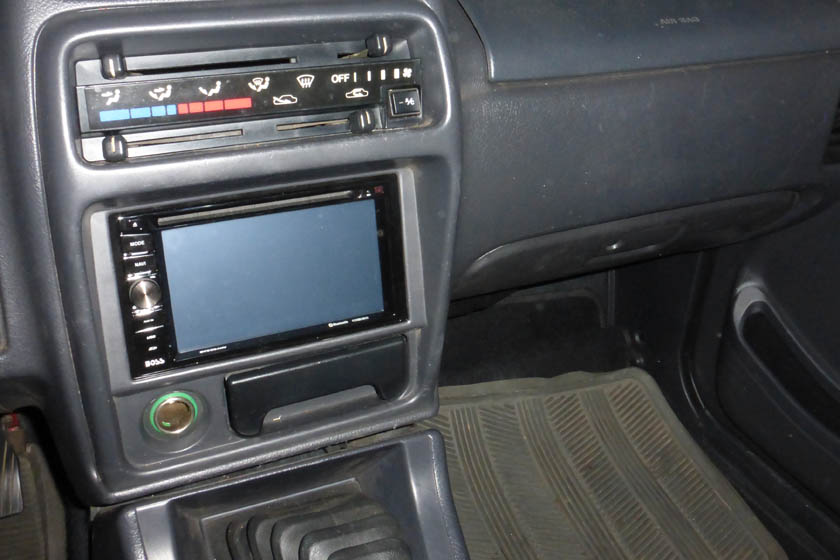
And here is my new radio which I just finished installing
Getting started on the installation was
a little slow, as I had to figure how to remove the plastic bezel
around the radio. On my Jeep, you just pulled it off and a number
of spring snaps would release. I gently tried that and it didn't
budge. I removed the ashtray and found 2 mounting screws, but
couldn't figure what else held it. Fortunately, my shop manuals
had arrived by now and it told step by step how to do it. It
turned out that I had to pull the 4 small knobs from the
heating/cooling panel, then pull the panel behind them out. There is a
raised section you can get hold of, and it pulled right out, held by
small clips. Now I could get at the remaining 2 screws holding
the bezel.
Installing the radio was fairly straight forward. It came with a
wiring harness that plugged into the rear of the radio and had about a
dozen color coded and labeled wires about 8 inches long. I also
bought an installation kit for my brand of car which also had a
connector and colored wires. By connecting all the similarly
colored wires between the two harnesses, I ended up with a pigtail
harness that plugged into the car wiring on one end and the radio on
the other. It is so much easier to
connect all those wires on
the workbench than to do it in or under the dashboard! After
connecting this harness, I only had two additional wires to hook
up. One was a wire from the backup lights to tell it to go into
backup camera mode, the other was a wire from the parking brake switch
to allow use of the DVD player. Of course the original car wiring
did not
support a backup camera or play video DVDs. I also had to plug in
the RCA jack for
the camera's video signal and connect an additional antenna for the GPS
reception.
The radio came with a pair of L shaped mounting brackets, with multiple
slots to adjust to just about any configuration. Unfortunately,
the mounting holes in the dash are farther apart than the height of the
brackets. I figured I would have to custom make a pair. I
then remembered a comment on one of the forums where a fellow used the
factory radio mounting shield to install an after market radio. I
got the original radio out and the mounting ears were connected to a
thin sheet metal box surrounding the radio attached with 2 screws
on each side. I removed it, put it on my new radio and the screw
holes even lined up with threaded holes in the radio. I installed
the shield and of course the mounting holes lined up and the radio was
perfectly located. There was even a rubber lined stud in the rear
that went into a matching hole under the dash to help support the
back. I'm glad I didn't let the seller throw away the old radio!
The radio does just about everything you might want it to, including:
- It plays AM and FM radio broadcasts
- It plays a variety of audio formats from a thumb drive with a front panel USB port
- It plays a variety of audio formats from an SD card in a front panel port
- It shows photos from the two above inputs
- It accepts an analog audio signal from a front panel 3.5 mm phone jack
- It plays CDs and DVDs in numerous formats. The DVDs will only play if the parking brake is on.
- It has a built in backup camera function
- It has a bluetooth link to connect it to your cell phone
- It will answer incoming calls. There is a built in
microphone to pickup your voice, and the other party plays through the
radio's speaker system
- It automatically links to your phone address book for making out going calls
- It automatically mutes what ever was playing when you start to use your phone
- It will play and control music from your cell phone
- It has built in GPS navigation
- Allows use of steering wheel buttons for control, if your car supports it (mine doesn't)
The radio sounds great and all the functions seem to be working as
advertised. One advantage of having the GPS is that the clock and
calendar are auto setting and should stay very accurate. My Jeep
radio lost about 1 minute a week and was a constant source of
aggravation to me- especially since it was part of a very expensive radio!
As with most everything I get, I would change a few things on this radio if I could, but really very little.
Dislikes:
- They offer 5 different "wallpaper" selections. Four of the
5 are battleship gray with different patterns. I selected the
only one with any color in it. (Although I think I can load my own backgrounds.)
- They have huge numbers for the frequency of your station,which
stays mostly constant, but a very, very tiny, short line for the RBDS or RDS (radio data system) - what is
currently playing and the artist; this only displays about 10
characters and slowly scrolls through. For some reason the radio labels this as "PS:"
- Whenever they display a list that you need to scroll through, it is
very hard to scroll without actually selecting the item where you first
touch your finger.
All in all, I am very satisfied!
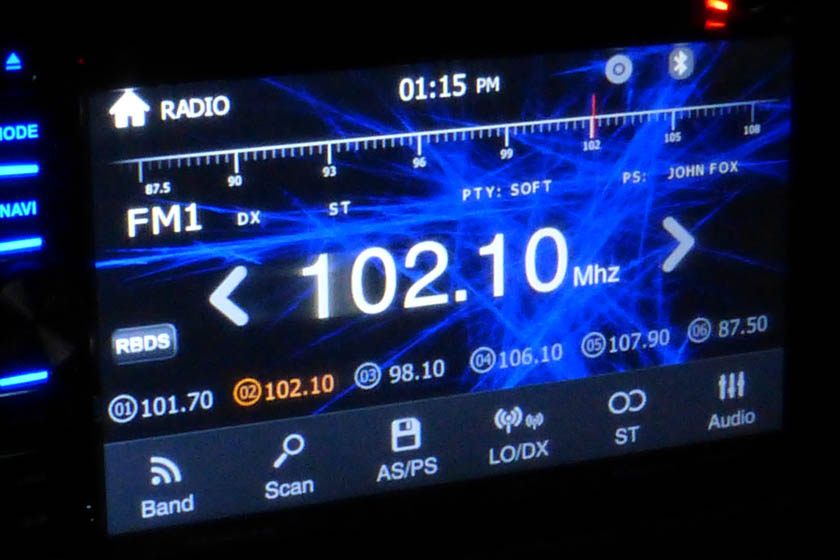
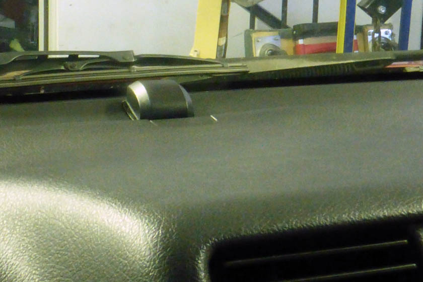
This is the main radio screen.
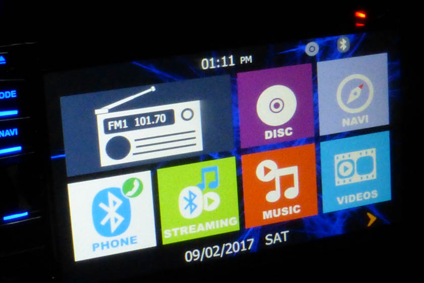
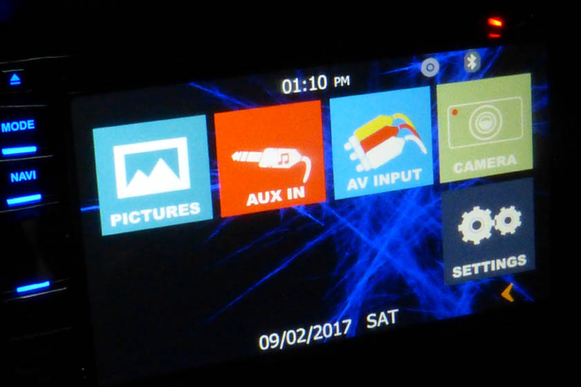
By tapping the home icon on the screen (little house) the menu comes up spread between 2 pages.
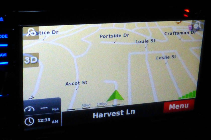
The navigation seems to work fine, but I still prefer my Garmin stand
alone units. Even if I limit myself to the Garmins, I always have
this in
case I need it. The only downside to the unit having GPS is I had
to mount another antenna. Here it is in the center of the dash
right at the windshield.
Installing the backup camera
Installing a backup camera on this car is really not a necessity as the
rear visibility of this car, compared to the other recent cars I have
had is excellent (except the view directly back is somewhat blocked by
the spare tire), but I really like the idea of having one - and the
ability is included in the radio at no added cost!
Having the radio that directly supports a backup camera is great, but
it is no good until you mount and wire the camera! That was not
as easy on this car as it should be. The wiring is currently in place, but
it seems that anywhere that makes sense to locate the camera has part
of its view blocked by the spare tire on the back door.
I looked at mounting the camera in the license light frame like most
cars do, and besides being way off center, the spare tire blocked part
of its view toward the passenger side. Mounting the camera inside
the rear window above the spare has the view downward blocked by the
spare, and the window tint would dim the picture. I almost
decided to mount the camera looking through one of the holes in the rim
between the "spokes". I wired up the camera and tried it in
various positions and it had to protrude well out of the rim to not
have any of the image blocked. This would also permanently
prevent the use of a tire cover.
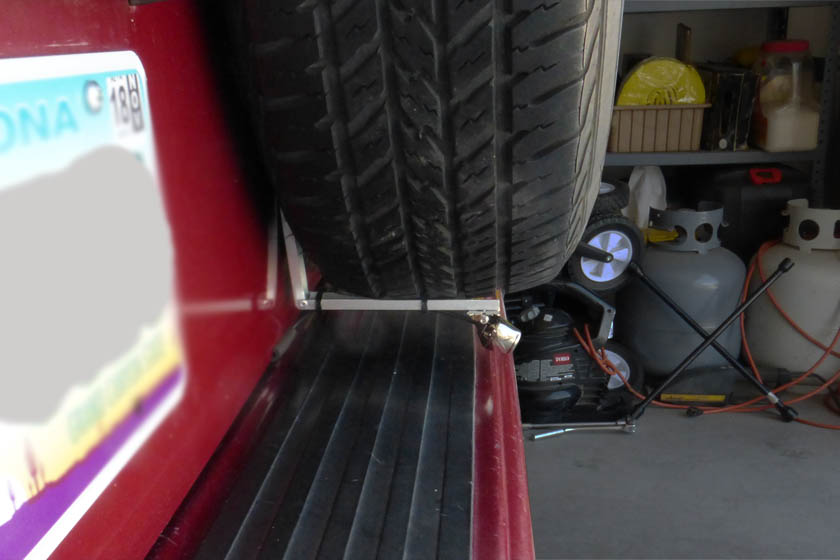
I finally decided to mount it between the tire and the bumper, under
the left side of the tire, centered on the car. I designed a
simple bracket that mounts on one of the tire holder mounting bolts and
hangs down between the door and the tire, then bends and runs along the
tread to the rear. I made sure that the bracket is flexed by the
tire to maintain a preload against the tire. This should prevent
any undue vibration. I routed the wire under the door edge then
up through the door bottom through a rubber grommet. The wire is
held tight to the door edge with a short length of split rubber
hose. This whole assembly swings open with the door and clears
the bumper in the process.
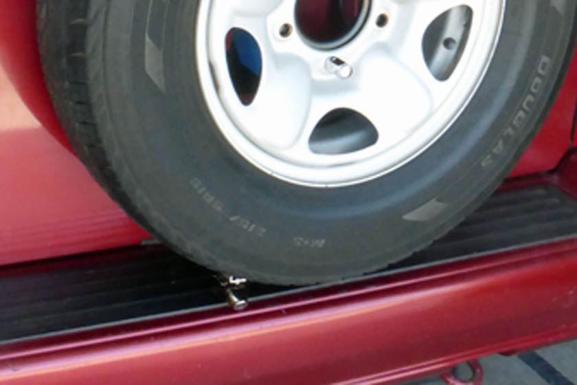
The left view shows how inconspicuous the camera is. It is hard
to tell in this shot, but the camera is very close to the center line
of the car. The right shot
shows the bracket. The only place that there is a close clearance
is where the wire passes under the door and is retained with the hose
(barely visible).
I will fasten the hose in place on the inside of the door with an adhesive after checkout is complete.
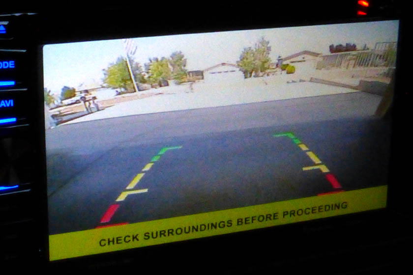
The resultant picture is very good. It is sharp and clear, and there is no obstruction of the image.