Dick Mason's Electric Vehicle (EV) Conversion ProjectPart 7 Additional Electronics Installation (Instrumentation, Charger) 10/17/08 thru 11/6/08
The work in this section was done as time was available
during
the previously described tasks. For clarity, it is written up
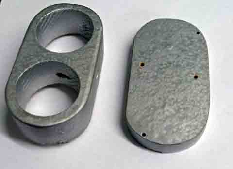
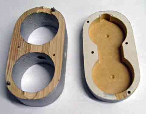
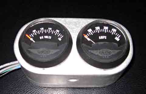
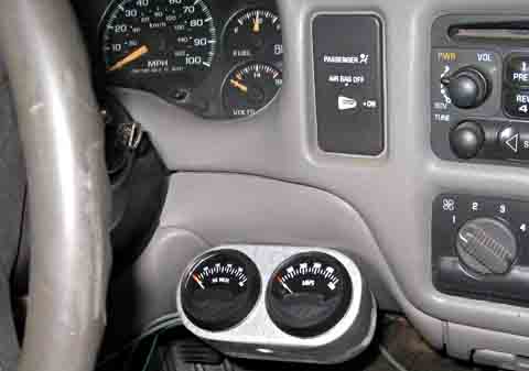
here as though it was done totally separately. Temporary Instrument Mounting I eventually hope to mount my electrical monitoring instrumentation in the original truck instrument package. As I am starting out with only the most essential instruments, measuring the battery voltage and the battery current, I decided to mount them temporarily until I have decided what I my final configuration will be. I used a piece of 2 x 4 and bored holes for the meters
and band sawed
the outside to an oval shape. I made a back plate (needed
because
of the high voltage on the voltmeter) from some composition 1 x 4.
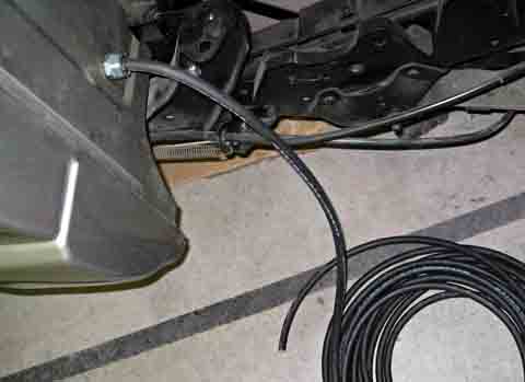
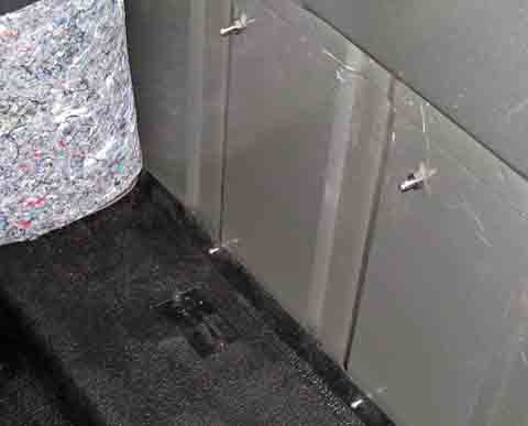
Battery Charger Installation The battery charger does not mount on the board, but behind the driver's seat. I removed the carpeting from the rear wall of the cab and drilled holes in line with the mounting holes of the charger. I installed bolts that are sealed with neoprene washers on the outside and a nut inside. The charger will slip over the bolts and be retained with lock nuts. I plan to cut the carpet as little as possible to allow me to complete the mounting The bottom bolts were quite a problem, as they came out
at about the
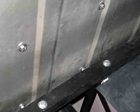
center height of the front battery box support cross member.
I had
to unbolt this bar and lower the front of the battery boxes using a
jack.
This allowed access the these holes. Once the bolts were in
and tightly
sealed, I re-bolted the cross member. This was quite a task
as the
weight of the batteries made it very hard to get the holes properly
lined
up.
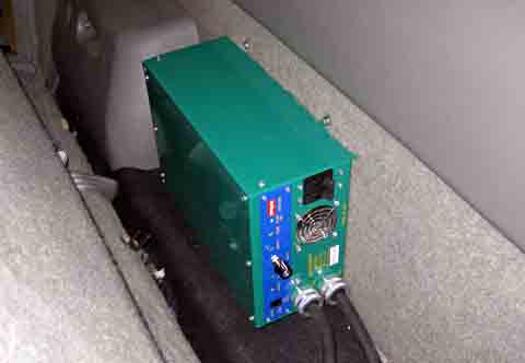
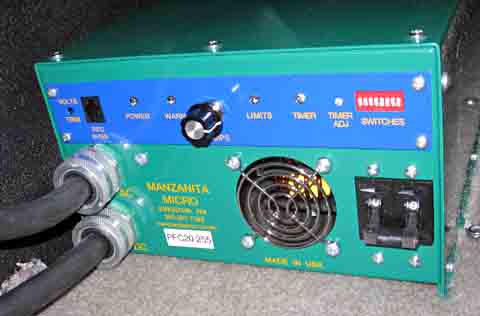
The charger, a Manzanita PF-20, is the best unit I have found. It is also about the most expensive. There are several advantages to it: 1. It is power factor corrected. This means that it is more efficient and uses less electricity to charge my batteries. 2. It operates from 110 v or 220 volts without any adjustments (actually, it can operate anywhere from 60 to 250 volts at 50 or 60 Hz).. I can charge at the maximum rate at home using a special outlet, yet still take advantage of any outlet that is offered to me. 3. It contains a "Throttle control", which is a knob that controls how much current it produces and also how much it draws from the line. This allows its use on a low capacity source by reducing the charge rate. 4. It is adjustable from 12 volts to 450 volts output. This means that if I change the battery voltage on my truck, or keep the charger for a future vehicle, I can just re-adjust the voltage and use it. On every other brand I researched, I would have to buy a new charger for a new voltage. 5. It has an excellent reputation in the
industry.
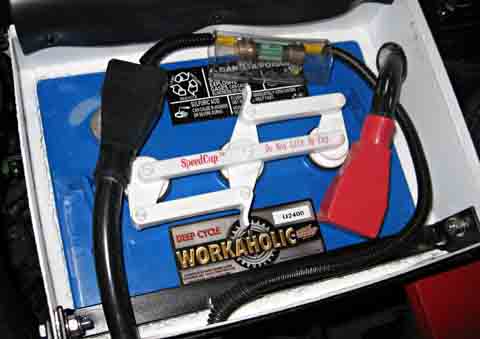
Charger Interconnections My next project is to finish the charger
installation. I decided
to connect the charger directly to the battery pack, instead of the
electronics
board as I first had planned. The charger manual repeats
several
times to never operate the charger without a load. If I
connect to
the electronics board, there is much more chance of having a connector
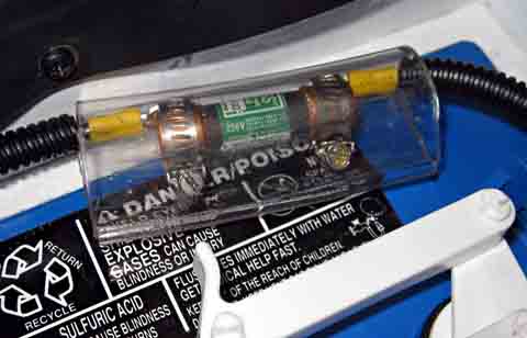
unplugged. Connecting directly to the batteries through two
heavy
fuses should help minimize the risk. The fuses are rated well
above
the charger output, and should be purely disaster prevention devices.
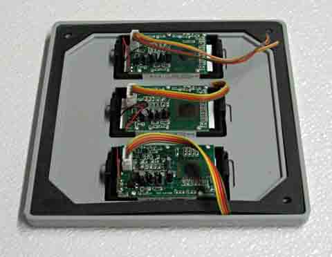
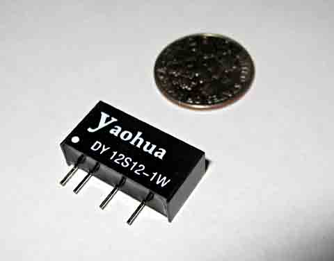
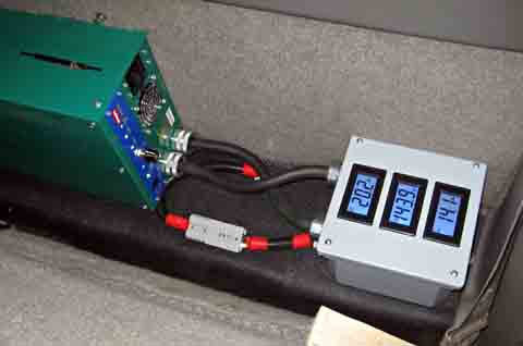
Charger Meter Box I had decided to fully monitor what the charger is doing during charging. To this end I ordered 3 low cost digital panel meters from an Ebay seller in China. These will monitor the AC current the charger is drawing, and the DC voltage and current it is producing. I felt there was really no need to monitor the incoming voltage. It should be either 115 or 230 volts, and I really don't care about the exact level. There is one main "gotcha!" with these meters. They are each powered by a 9.5 to 12 volt AC or DC source. This power must be totally isolated from the circuit being measured and from the power supplies to the two other meters. Each meter must have its own isolated power source. My first thought was to see if I could find 3 switching "wall transformer" power supplies that produced an output in my voltage range. The local Habitat for Humanity thrift shop has a large carton of these power supplies. My first observation was that most were for cell phones and had an output between 3 and 5 volts. I wanted to limit my search to switching type supplies, as most of them will handle an input of either 115 or 230 volts without any change. I want to power everything from the line cord I use to charge the car, as any other method would be unduly complex. What I ended up finding were 3 almost identical power supplies that were labeled as having an output of 5-11 volts. I didn't know just what that meant, but I bought them at $1 each. What I found was that two of them output about 5.4 volts, and the third 6.4 volts. Apparently there is a way to adjust the voltage at the manufacturing stage. I tried comparing component values between the two different voltage models, but could not appreciably raise the voltage by further changing the parts that were different, so I did the logical thing: I gave up! I then ordered 3 DC to DC converters from the same
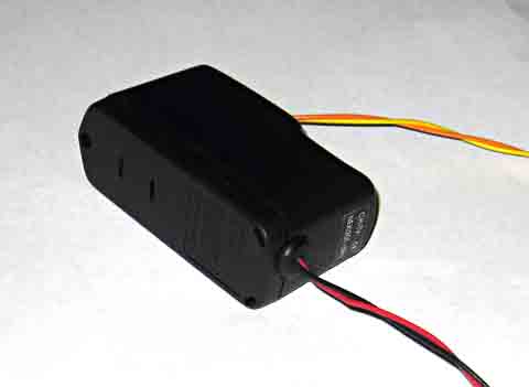
outfit in China.
These are very small modules that accept 10 to 16 volts in, and supply
12 volts - totally isolated - out. The vendor gave me a 30%
discount
and they cost me $7 each with free shipping. OK, now I have a
way
to turn 12 volts into 3 isolated 12 volt supplies. Where is
the original
12 volts? I did not want to use the truck 12 volt battery, as
this
would be a nasty wiring and switching problem. I decided to
use two
of the "wall wart" units I bought and hook them in series.
5.4 volts
plus 6.4 volts is 11.8 volts. This is well in my
range. In
addition, I can use the output of these supplies directly with one
meter
(it is already isolated), and use the DC to DC converters with the
other
two. This leaves me a spare.
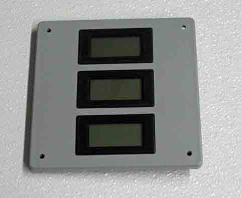
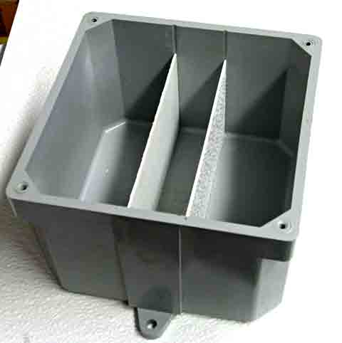
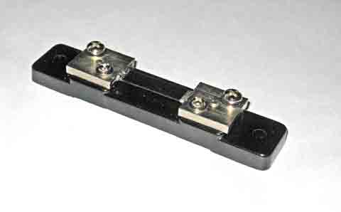
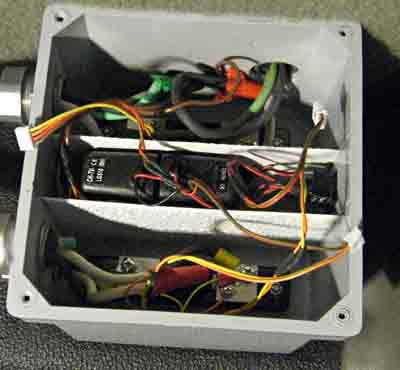
I was originally going to use standard AC wiring boxes to make all the AC and DC connections and to hold the shunts for the ammeters, with a separate smaller box on the charger case to hold the meters themselves. Once I received the meters and shunts, I found the shunts would not fit in any standard box I could find. I had bought a 6 x 6 x 4 heavy plastic box with a lid earlier in the project for an idea that did not pan out. This was ideal for mounting all the connections, power supplies, shunts, and the meters. It would also fit on the ledge behind the driver's seat just like the charger, holding the meters in an easily viewable position. I machined cutouts in the lid for the 3 meters, and very
laboriously
managed to hand cut 4 grooves down the side walls of the box to help
support
two dividers. I want separate compartments for the AC shunt
and interconnections,
the meter power supplies, and the DC shunt and
interconnections.
I made walls that came up 3/4 of the height of the box, allowing plenty
of room for the power supply and meter connections above them.
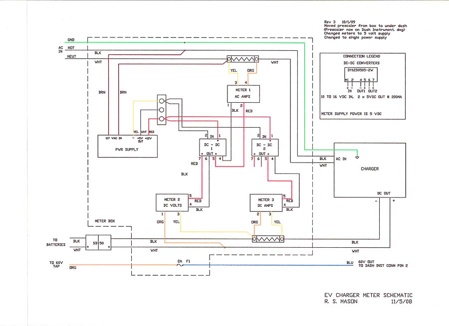
This is the schematic of my finished meter box. Note of 2/6/09: This schematic has been updated from the original to show the inclusion of the E-meter prescaler and other wiring changes needed for the instrumentation added after this original build. Note
of 9/26/09: The schematic has again been updated to remove
the
E-meter prescaler and to change to LED type meters after an unknown
event destroyed 2 of the original meters and a dc-dc converter.
See EV section 10 for details.
To go the the next section, click here. |
||||||||||||||||||||||||||||||||||||||||
|
Dick
Mason, Prescott, AZ 10/14/08
|
 .
.