Dick Mason's
Electric Vehicle (EV) Conversion
Project
Part 8
Finishing Touches
11/1/08 thru
Present
This section covers items done to complete the job, and
are mostly mechanical
in nature. Not all of this work is being shown in
chronological order,
as some of it was done during lulls in the mainline tasks, and others
were
done as parts arrived. For clarity, this writeup is shown as
if the tasks were worked continuously.
Rear Suspension Air Bag Installation
The truck had rear air shocks, installed by a previous
owner, when I
bought it. By pumping them up to the maximum of my compressor
(about
150 psi), I was just able to compensate for the roughly 1300 pounds of
batteries I added under the bed. This is a higher pressure
than can
usually be found, and the very small volume of the shocks drops the
pressure
rapidly with even the smallest leak in the system. I was not
comfortable
with this approach, so I ordered a pair of rear supplemental air
bags.
They arrived and I installed them during the same time frame as the
electronics
installation. It appears that about 40 psi in the air bags
will set
the height of the truck rear at just about the pre-conversion
height.
I can vary the air bag pressure to position the rear from several
inches
below this to several inches above it.
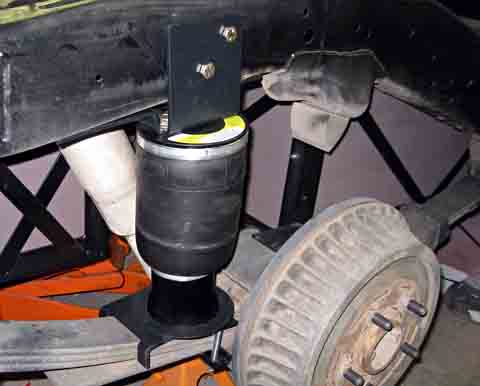 |
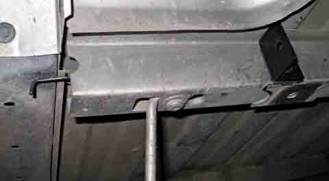
The air springs mount between the spring and the
frame. I had
to drill 2 holes in the side of the frame on each side.
Otherwise
it was simply a bolt-on installation.
I have separate fill valves for each side mounted
on the rear bumper,
along with the fill valve for the air shocks.
|
Tilt-up Bed Installation
The next project was to remount the bed to the
truck. As I plan
to hinge the rear of the bed and add air springs to make a "tilt-up"
bed,
there is a lot of work to do. When done, I will be able to
tilt the
bed up, somewhat like a dump truck, to access the batteries under
it.
I bought a kit for this bed tilt. It included a pair of husky
hinges,
two 200 pound gas springs, and a pair of formed reinforcement
plates.
Unfortunately, the reinforcement plates are apparently for older
models
of the S-10 pickups and they would not fit mine. As I show
below,
I figured out how to modify them to work for my truck.
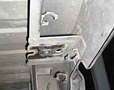
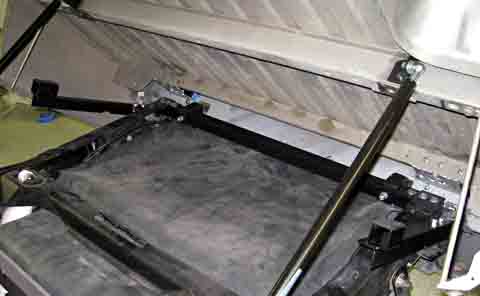
| This is the underside of the bed in the area I
will be mounting the
hinges. The rear flange of the bed is shown at the
right. The
hat section runs the width of the bed and has a pair of these mounting
plates where the rear of the bed originally bolted to the frame.
I plan to mount the hinges to the outside of the
bed rear flange and
have the bolts extend through the bent down leg of the mounting bracket
and through an added reinforcement piece above it.
|
 |
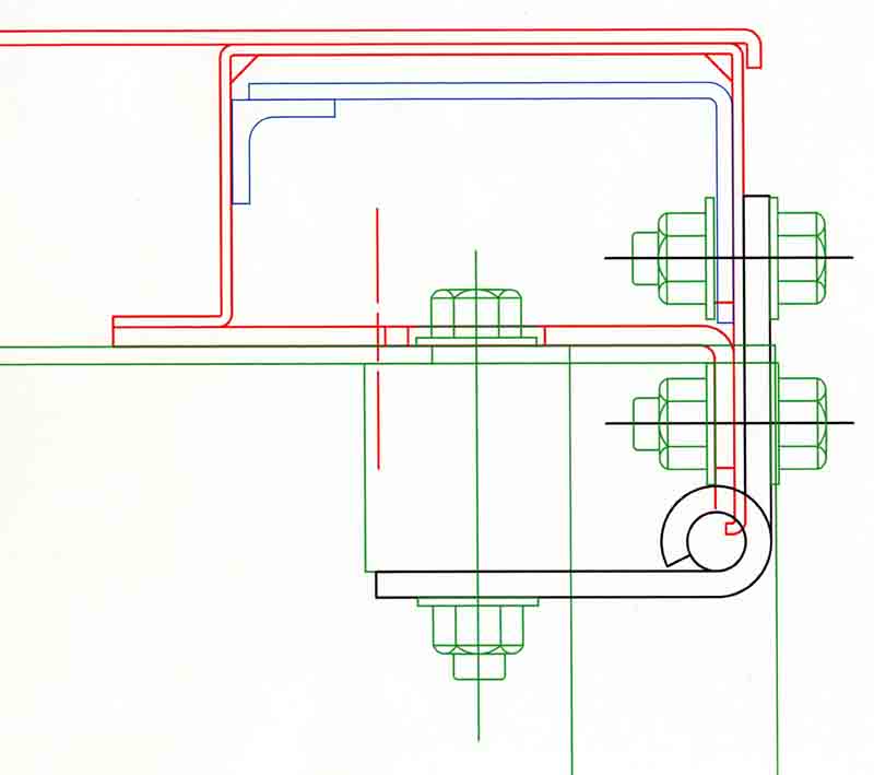 |
This is a cross section of the hinge mounting.
The
red is the bed and the hat section with the stock bed mounting plate as
shown in the last photo. The blue is the added reinforcement.
It
is cut from the reinforcement sent by the kit vendor, that apparently
fits older models. I cut it and welded an angle to
it. The
angle is bolted through the left of the hat section.
The top
half of the hinge bolts through the bed rear flange as well as the
flange of the original bed mounting plate (bottom bolt) and the added
reinforcement plate (Top bolts). The bottom half has 2 bolts
through the frame and square cross member that holds the battery box,
and a third bolt through only the square cross member and a doubler
plate on the top.
|
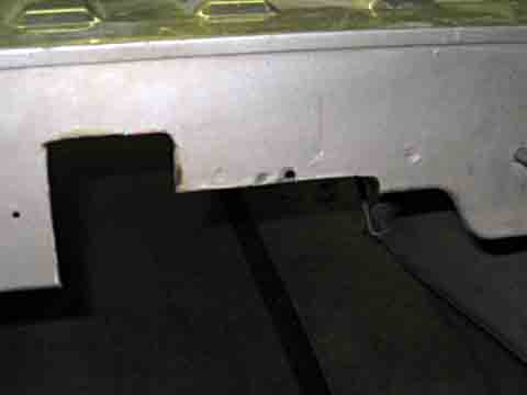
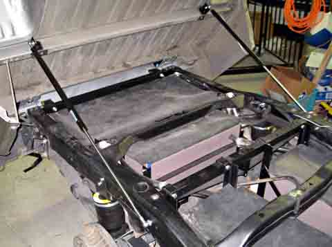
| With the bed almost flat on the floor, I started
to make the cutouts
in the bed rear flange to clear the battery box mounting structure, the
hinges, and the battery boxes. |
 |
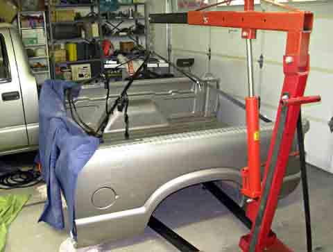 |
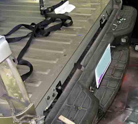
Now it is time to actually put the bed back in
place on the truck.
I have attached straps to the tie-down eyes and
have my engine hoist
ready to lift it and roll it into position.
I have removed the rear tire to provide more
clearance and mobility.
|
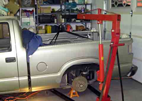
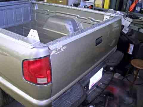
| Here the bed is in place on the truck
frame. It really was not
very hard to do, even though I worked alone. |
 |
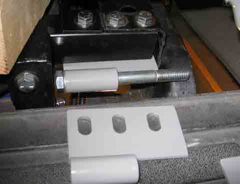 |
I have machined the mounting slots in the bottom
of both hinges.
Here the right one is mounted and the left one is shown to illustrate
the
mounting slots.
The right two bolts pass through the frame and the
cross member.
The left bolt just goes through the cross member and a doubler plate on
top.
I figured I needed to provide slots to enable an
accurate adjustment
of the bed position.
|
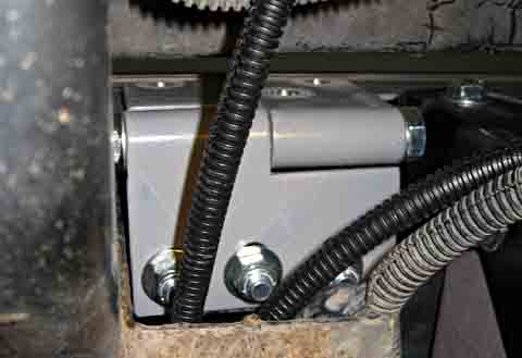
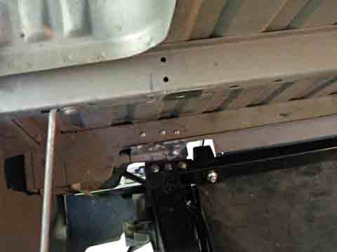
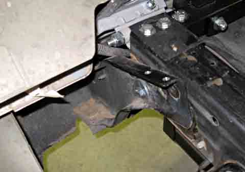
| Under the truck looking upward shows the mounted
hinge. The three
bolts pass through the 1 1/2 square cross member and two of them
continue
on through the top frame rail.
This view shows (if you look carefully) the
drilled top half of the
hinge in position for bolting.
The structure at the top of the picture (behind
the hinge) is the rear
bumper.
|
 |
 |
I cut out two pieces of neoprene and contact
cemented them to the frame
tops. I will do this on all the 8 original bed mounting
locations.
Hopefully this will keep the bed from rattling while driving. |
| This shows the hinges fully installed
(almost). I found I only
had two 1 inch grade 5 plated bolts left, so they are
installed.
The dark bolts are merely pushed into the holes. I will pick
up the
correct bolts at the hardware store this afternoon. |
 |
 |
The correct bolts are installed and tightened.
I have replaced the tail and license plate lights,
and they all work!
I also installed the tailgate, after using a ball
pein hammer to artistically
create some clearance dents where the hinge mounting bolt heads
interfered
with the bottom corner of the inside of the tailgate.
It is getting close to being a truck again!
|
This is my progress through 11/15/08
Tilt Bed Gas Spring Installation
It is now into December and I have been driving the
truck for several
days. It is time to finish the work on the tilting bed.
I used my engine hoist and a nylon strap to tilt the bed
into the approximate
"up" position and used a board which I notched to keep it from slipping
out of position to hold the bed safely in position. I then
started
swinging arcs for the gas springs in both the compressed (down) and the
extended (up) positions. This gave me an approximate mounting
position
for both ends of the cylinders.
I wanted to mount the upper end on a stiffener which
runs across the
bed a couple feet forward of the hinges. The bottom end would
be
attached to the frame a couple of feet forward of that.
| I have drilled the two mounting holes for the
upper bracket on this
side. The problem here is that I have very limited access to
the
inside of the hat section.
I decided to use a doubler plate/nut plate on the
inside which I would
insert through an opening in the end of the hat section.
Using a
heavy wire welded to it, I will position it behind the holes so I can
start
the bolts into its threads
|
 |
 |
This is one of the upper mounting brackets and
the threaded doubler
plate. As you can see the wire to allow me to position it is
quite
long. |
| Here the bracket is bolted in place with the
doubler on the rear side
of the sheet metal. My positioning wire worked
well. I gripped
the exposed end with a pair of Vice Grips and it was easy to position
the
doubler to start the bolts.
I will leave the wire attached for any future use
and will push a piece
of foam in the hat section around it to keep it from vibrating.
|
 |
 |
I have mounted the upper brackets, determined the
location for the
holes through the frame, and mounted the gas springs.
They work well. Maybe too
well! I have to really pull down
hard to close the bed. The only hard thing about opening it
is stooping
over to grab the bottom of the bed to lift it. The lifting is
then
quite easy.
|
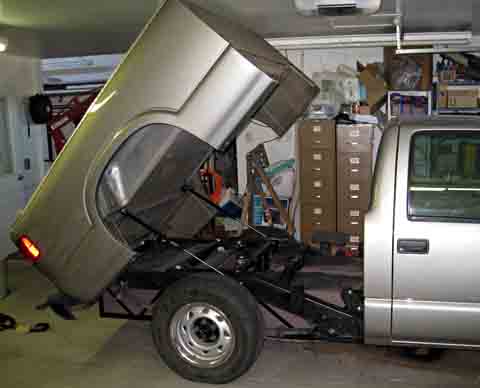
| Here the bed is up! I have better than
a 45 degree lift and it
looks like my access to even the very rear batteries will be
OK.
I have pulled the caps from the very rear batteries, and can clearly
see
the water level in these cells. That's all I need!
If I were to increase the lift any, I would not be
able to raise the
bed in my garage. As it is, I have to make sure to clear the
light
fixtures and the door opener.
I still need to check the bumper clearances in all
positions.
Right now, I have lowered the bumper enough to clear everything.
|
 |
Tilting Bumper
It turns out that there would truly be an interference
between the bed
and the bumper when the bed is lifted, if the bumper were to stay in
its
normal position. The answer is to lower the bumper as the bed
is
raised.
I implemented a variation of the solution described by
the vendor of
the tilt kit. I pivoted the bumper about one of the bolt
locations
allowing it to drop under its own weight, and provided a means for the
bed
to lift it back to the normal position when the bed is lowered.
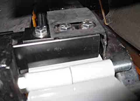
I started by making a sleeve bushing similar to the ones
I used on the
electronics board, only much larger and more robust. I
installed
these in one of the bolt holes where the bumper bracket originally
bolted
to the frame. After installing one on each side, the bumper
would
pivot freely between a position several inches lower than normal and
the
normal position.
I then made extension bars that fastened to the brackets
and extended
forward
to the bed cross stiffener where I attached the gas springs.
When
the bed is lowered, this cross member presses down on a spacer on the
extension
bar and presses it down, raising the bumper to its normal position.
 . . |
I have installed a heavy duty pivot in one of the
bracket bolt holes.
The bumper now lifts freely and readily drops from its own weight.
The bottom position is limited by the bumper
contacting the battery
rack framework. I installed neoprene on the framework as a
soft-stop.
|
| This shows the complete bumper lift
system. The two extension
bars reach forward to the bed cross member in the foreground of this
picture.
When the bed is lowered, the cross member contacts neoprene pads on the
spacers at the end of the bars. It continues pressing down on
the
bars, lifting the bumper. |
 |
Charger Port
Next I decided to finish the charger port. Up
until now, I have
been driving with a hardwired 50 foot power cord coiled in the bed.
Even though the power cord to the charger enters the
truck cab just
a couple feet from the gas filler location where the charge port is
going,
I had to run the wire to the rear of the truck along the frame, then up
to the bed and forward within the bed structure to the charge
port.
This is to allow the bed to tilt up.
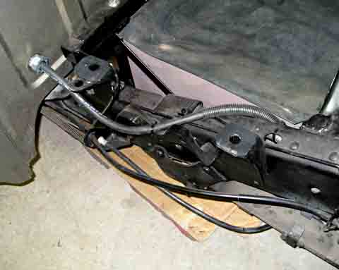 |
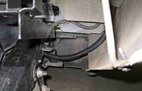
The wiring from the cab is routed within the
frame to the rear of the
truck. |
| As the wiring reaches the rear of the truck it is
routed over to the
bed where it runs forward over the fender. There is also a
smaller
cable of 2 wires from the filler lid switch which runs forward to the
hairball. |
 |
 |
I originally could not find a panel mounted plug
at the local electrical
supply houses, or on Ebay, so I was going to jury-rig a cable end plug
in the filler cap opening. I decided I did not want that, so
I kept looking. I finally
found what I wanted at a supply house in North Carolina.
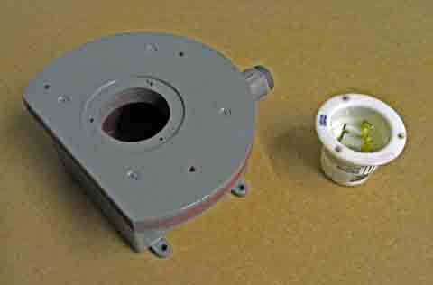
I made a mounting plate from a scrap left from the
electronics board.
I mounted a weatherproof electrical box to the rear and made provisions
for mounting the plate to the gas filler opening and for mounting the
flange
mount plug. I had to recess the plug slightly to prevent the
filler lid from hitting it.
|
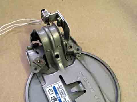
| I made aluminum brackets that mount on the gas
filler lid. They
mount a weatherproof microswitch that is positioned to activate when
the
cap is closed.
Opening the lid pulls the rounded hinge bracket
away from the switch
causing it to open.
This switch connects to the hairball and prevents
operating the car
if the lid is open. Therefore it should be impossible to
drive off
with the power connected.
|
 |
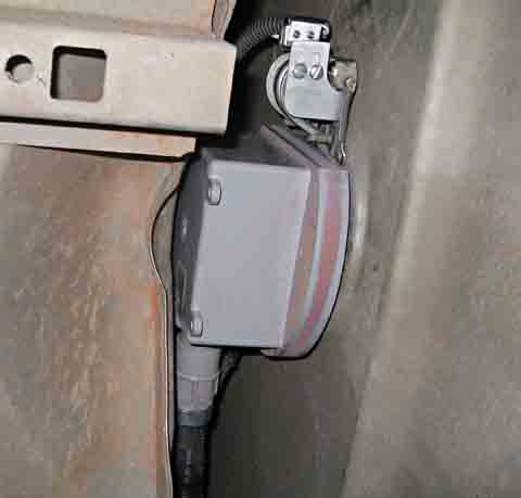 |
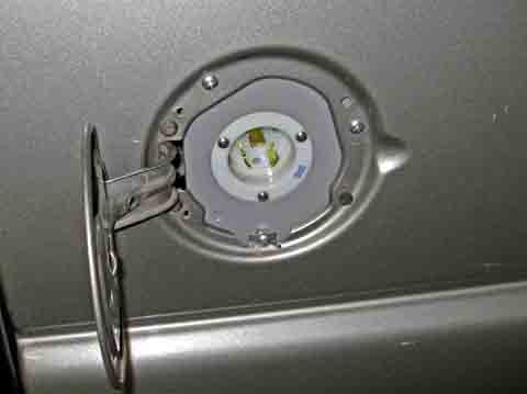
The finished assembly mounts behind the gas
filler cap with 3 screws.
The main cable, which runs in an opening over the fender, enters
through a sealed
fitting. The smaller 2 conductor cable connects to the lid
switch
at the top.
I
originally painted the assembly red, as I thought it would look good.
It didn't, so I repainted it gray. The red shows
through
some on the board edges. |
| Here is the finished charge port. It
accepts a 3 prong twist
lock receptacle type L6-30, which is rated for 250 volts at 30 amps. |
 |
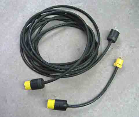 |
I made cables to use for charging. The
top long one is an extension
cord with a twist lock connector at each end. This will
directly
connect the charging outlet in my garage to the truck.
The short cable is an adapter which has a 20 amp
115 volt plug on one
end and a twist lock receptacle on the other. It allows me to
plug
into any conventional 115 volt outlet.
|
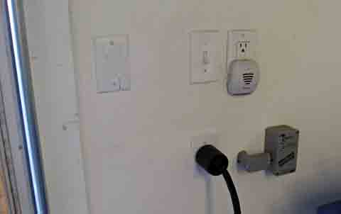
| I finished installing my charging outlet in the
garage. It is
a 30 amp 240 volt circuit. |
 |
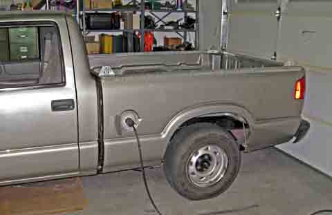 |
And here is my truck being charged with my
finished
setup. The twist-lock
extension cord is plugged into the garage outlet and the
truck. I
can now charge up to about 20 amps into the batteries. |
Electronics
Board Prop Rod
Up
to this point I have been using a notched and drilled 1 x 2 board to
hold up
the electronics board while I was working on it. This worked
fine, but required carrying the board with me at any time I wanted to
hold up the board.
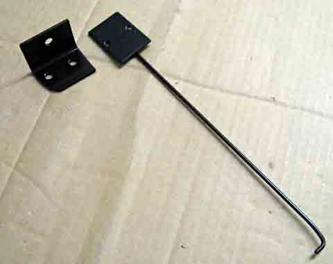
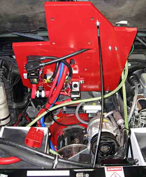
I decided to try making a prop rod similar
to that used to hold up the hood. I found a length of 5/16
rod
that was long enough. I drilled a hole on the rear side of
the
upper radiator support bar. The hood prop rod is on the front
edge of this support. I used a vinyl grommet in the hole to
isolate the rod and keep it from rattling. I formed a double
bend at the bottom of the rod. By feeding the rod through the
grommet I had a pivot and a support for the weight of the board.
I made a couple of slight bends in the rod to better fit the
parked position.
I machined a small aluminum cup that is screwed to the bottom of the
board to confine the top end of the rod.
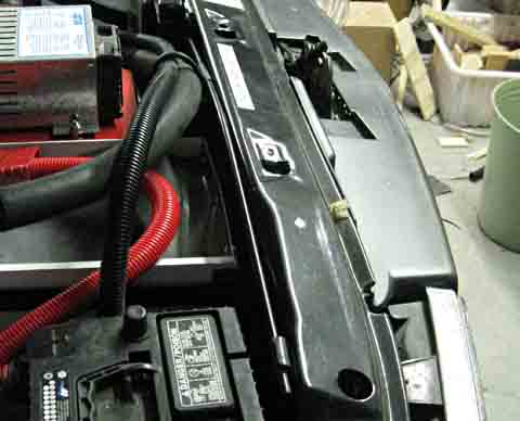
The
prop rod is inserted in
a grommet on the rear of the radiator support, and runs along the
length of that support. The end hooks under a headlight
clamping
tab.
|
|
|
|
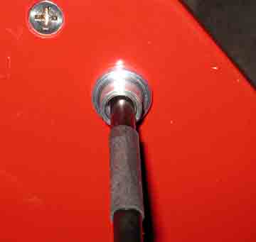
In use,
the rod is lifted and the end secured in an aluminum retainer cup on
the bottom of the electronics board.
Although it looks like the weight of the board is really bending the
rod, it is not. The bends were
made for a better fit when the rod is stowed on the radiator support
bar. |
Completion
Defined
As
most of the essential tasks have been completed and I am now driving
the truck regularly, I am going to define the truck as "complete".
This is not to say that there are not a number of additional
items needed and existing item that will need changing, but I have to
draw the line somewhere. As an engineer, I feel there is no
task
that is ever complete - it can and should always be improved.
This task is no different, but any additional changes or
additions are simply being defined as "post completion", and will be
covered in part 9.
<BACK>
|