Dick Mason's Electric Vehicle (EV) Conversion ProjectPart 6 Installing the Electronics Board 10/14/08 thru 12/3/08
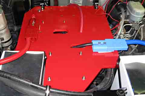
This page, Part 7 and Part 8 are pretty much in chronological order within each page, but due to parts availability and other factors, work was being done on the three sections a bit at a time. The charger and instrumentation work was done during breaks in the electronics board tasks, as was the work on the truck bed. The writeup here is as though each task was started and proceeded straight through to completion. This should make reading about the tasks clearer. Electronics Mounting Board Most of the electronics modules will mount on a board
under the hood.
I have already mounted the hinges for this board in a previous
section.
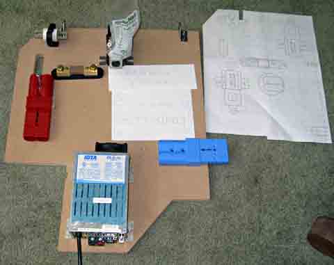
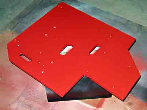
Using my cardboard template, my CAD layout, and predetermined
dimensions,
I cut the 3/4 MDF board to shape. I verified the positions of
the
components from my layouts and started drilling mounting and cable
access
holes.
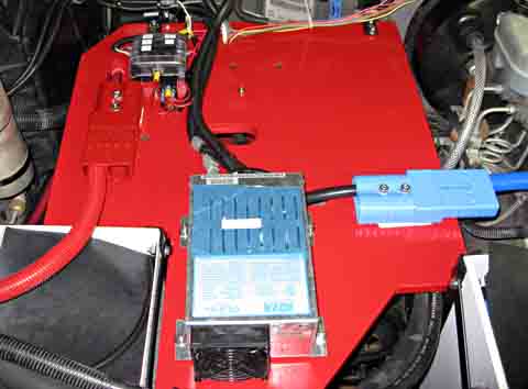
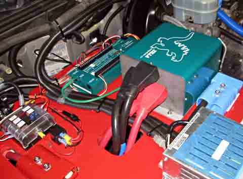
I mounted all the high current components I have and
started making
their cables. I made all the cables I can until I receive the
controller.
Finishing Electronics Board
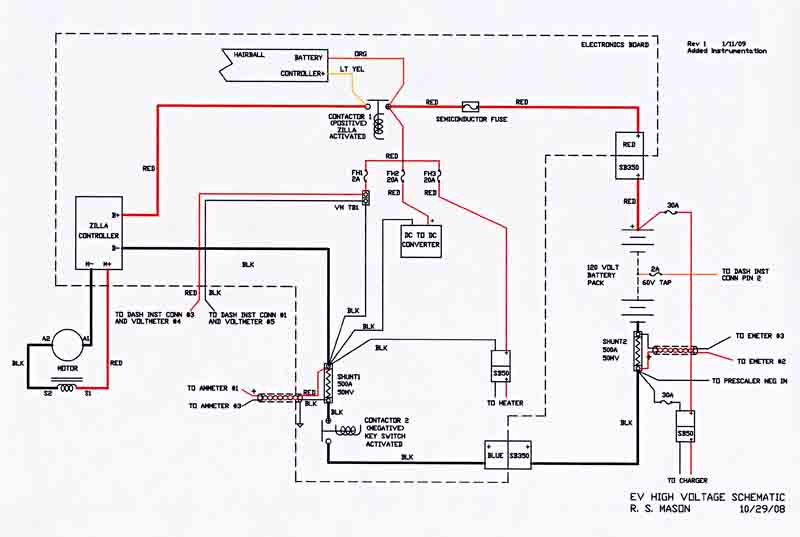
Electronics Board Wiring My next task was to complete the wiring of the electronics board to the extent possible prior to receiving my controller and interface, and to install it in the vehicle. Of course, after installing the board, there were a number of additional wires to truck mounted items that needed to be connected. Prior to completing the wiring, I spent quite a bit of time finalizing the schematics of both the high voltage and the low voltage portions of this board. I then did the physical wiring. For safety sake, I tried to keep most of the high voltage wiring on the bottom of the board and most of the low voltage on the top side. My finalized (as of this moment) schematic of the high voltage (120 volt DC) portion is shown here. Note of 2/6/09: These next two schematics have been updated to reflect the changes needed for the added instrumentation which was installed well after the initial build.
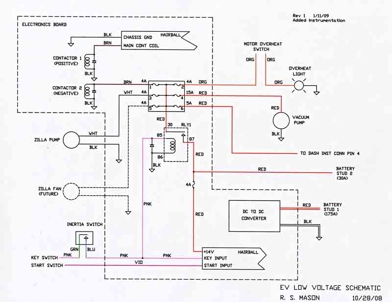
And here is the low voltage one (12 volts DC). (Also updated for the added instrumentation)
This is about as far as I can go with the drive electronics until I receive my controller. This is my progress through 10/30/08
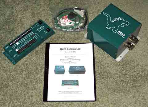
NEWS FLASH! (November 17, 2008) My controller arrived a couple of hours ago!
Unfortunately, I
have a commitment for the next week, but I will be able to get right to
work next week.
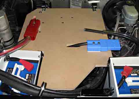
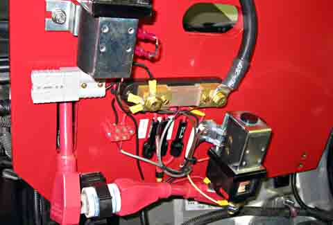
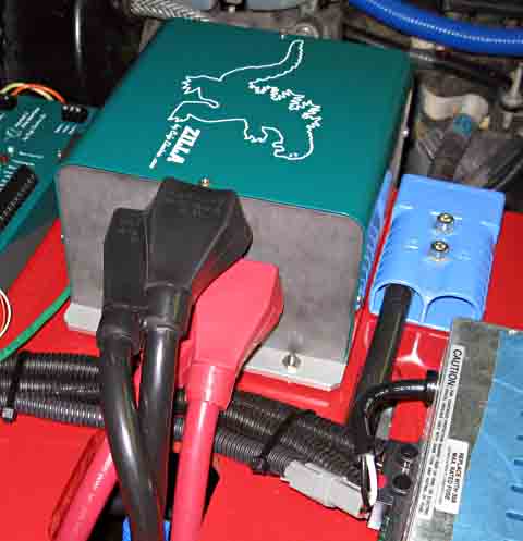
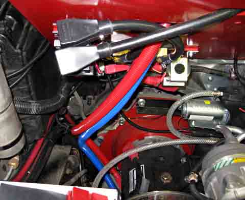
It is now almost Thanksgiving and I am back after spending a wonderful week with family in California. Board Modification and Controller Installation I had originally planned to run the motor cables over the top of the electronics board and down at the firewall. Reading the controller manual I found they recommend keeping the signal wires and the power cables a foot apart. Most of my signal wires run along the rear of the board along the firewall. To even approach this separation, I need to pass the motor cables down through the board right next to the controller. I removed the electronics board and removed all the components and wiring. I then enlarged the pass through hole in the board to accommodate two more power cables. I also enlarged a small hole I use for low current wires to pass through the board. After touch-up painting, and installing the controller mounting screws, I re-mounted all the components and wiring, and installed the board back in the truck. After mounting the controller and hairball, I made my
final two power
cables that attach the positive contactor and the shunt to the
controller,
and terminated the two motor leads and attached them to the controller.
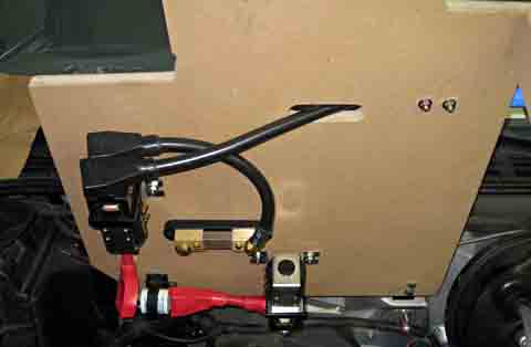
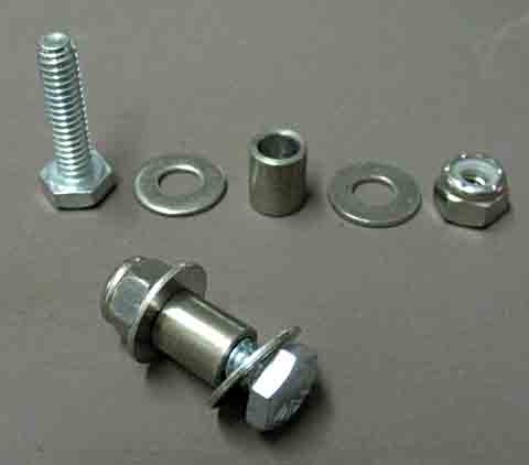
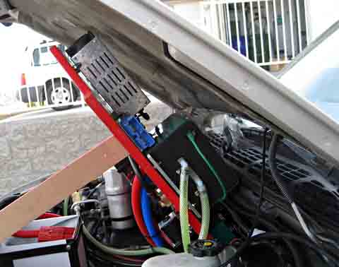
Electronics Board Hinge Modifications I knew all along that the hairball clearance to the windshield wiper motor was going to be a limiting factor on how high I could raise the electronics board. After completing all the re-installation and the addition of the controller and hairball, I tried lifting the board. I was quite disappointed in the reduced amount of lift I could now get. I went back to my CAD layouts, entering the exact location of the hairball and the windshield wiper motor, and experimented with moving the hinge point. I fount that by moving the hinge point forward 2 inches and up 1/2 inch, the board would lift about 50% higher. It probably will lift more than the open hood will allow. I designed a pair of adapters that bolt to the original
hinge halves
on the firewall and extend the hinge points to the new
locations.
I then made new brackets that mount on the board to provide the other
half
of the hinges. The board now rests in the same position as
before,
but pivots about a different point when being lifted.
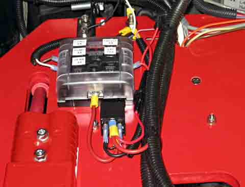
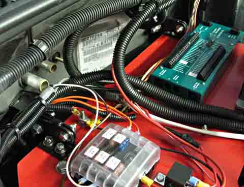
Completion of Wiring Now that the board is mounted (hopefully) for the final
time and I have
good clearances, it is time to complete the wiring of the
board.
The main circuits that need completion are the various signals into and
out of the hairball. These include things such as power and
ground,
ignition and start circuits, the throttle wiring, the speed control
wiring,
the control to activate one of the contactors and several connections
to
monitor existing signals.
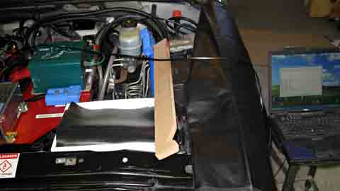
Preparing for the First Drive Now that the wiring is complete there are only a few items left before I can give the truck its inaugural test drive. I need to program the controller, plumb the controller cooling system, fill it with antifreeze, and run some preliminary tests. Programming the Controller Before I can use the controller, I must program certain
parameters into
it. This is one of the big advantages that convinced me to
use this
system. I used my old laptop computer to do this.
Some of the
parameters are the maximum current allowed to be taken from the
batteries
and to the motor, the minimum voltage allowed, the maximum RPM of the
motor,
etc. There are also a number of functions which can be turned
on
or off. In all there are about 27 programmable
items. In addition
it is equipped to output streams of data while you drive which can
provide
many performance readings as well as diagnostics. I have not
yet
really investigated all that can be done here, but it is extensive.
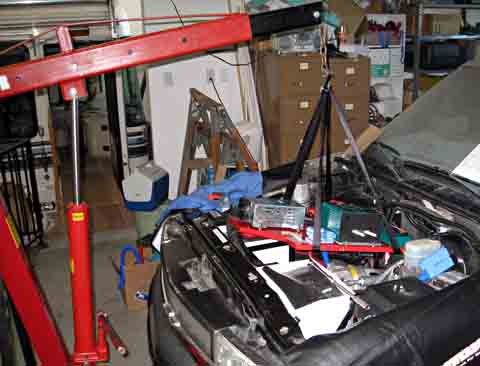
Controller Cooling System The Zilla is a liquid cooled controller. To this end I have installed a recirculating pump and a small radiator. I needed to connect flexible vinyl tubing between all these parts. In addition I included a squeeze bulb to use for priming the system. After connecting the hoses, I gradually added an antifreeze and distilled water mix to the radiator. I then pumped the bulb to force the solution all through the system, frequently adding coolant to keep the radiator full. It took a while, but I finally got all the major air bubbles out, with only a fine foam at some of the high points. I now started the pump which continued to circulate the fluid gradually letting the remaining air collect in the radiator and rise to the reservoir. Pre-operation Test Before applying full voltage and current to the system, I wanted to check that everything is functional while maintaining full safety. I pulled one of the motor leads from the controller and connected a 60 watt light bulb between the controller and the motor. For safety's sake, to turn on the controller, you must turn on the ignition, then activate the starter position for a couple seconds. Once activated, the power is applied, the throttle is active, and you can then drive. I tried to energize the system to verify that the bulb would light. My first several tries failed. I then remembered that to activate the starter, you must fully depress the clutch pedal. Once I did that, there was a clunk of the second contactor and as I pressed the accelerator, the light bulb lit. The harder I pressed, the brighter the bulb. Test OK! FIRST TEST DRIVE !!! (December 1, 2008 3:20PM) I was now ready to try it out. To memorialize this historic event, I set up my camcorder on a tripod in the garage and taped my first drive. I got in the truck and remembered to press the clutch while going through the ignition on - start switch sequence. Then I put it in reverse and slowly backed out of the garage. I drove around the block and pulled back into my garage. It was successful from the point that I made it out, around, and back safely. The downside was that my performance was abysmal. I was never able to draw more than about 100 amps, and had to shift down to first to make it up the hill on the block below mine and again up the driveway. I then reviewed the settings I programmed into the controller against a sample in the manual and realized I had been far too conservative in a couple of my settings. I changed these settings and the following morning I drove it again. This time it was much more satisfying. It is certainly no speed demon, but has almost reasonable performance. I was now able to pull up to about 300 amps, with the corresponding improvement in performance. I will continue to fine tune the parameters over time. Note of December 3:
As the under-hood work is basically done, I re-installed
the hood.
Now I am able to see how well my modified hinges are matched to the
hood
opening. It is almost perfect. The board lifts just
to the
point where it almost touches the hood when both are lifted to the
limits.
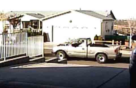
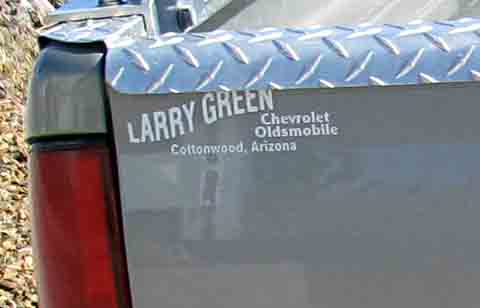
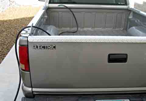
I took this opportunity to remove the plastic lettering
advertising
the original selling dealer from my tailgate. I hate those
ads!
In its place I installed one of my new "ELECTRIC" emblems. I
think
that looks much better.
Although I have now driven my truck, it is by no means
done. I
still need to finish the lift bed installation, the charging cable
setup,
the cab heater, additional instrumentation, etc. Later
sections will
cover these items.
This is my progress though December 3, 2008 To go the the next section, click here. |
|||||||||||||||||||||||||||||||||||||||||||||||||||||
|
Dick
Mason, Prescott, AZ 10/14/08
|