Dick Mason's Electric Vehicle (EV) Conversion ProjectPart 4 Mounting of Accessories 9/21/08 thru 9/30/08
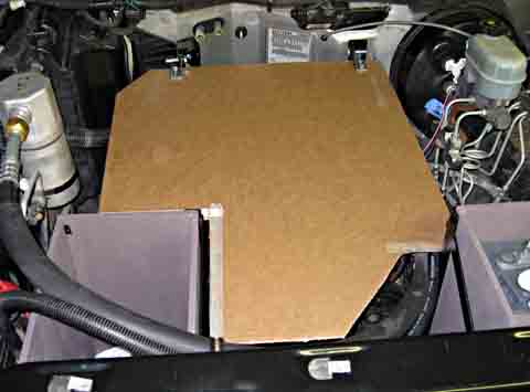
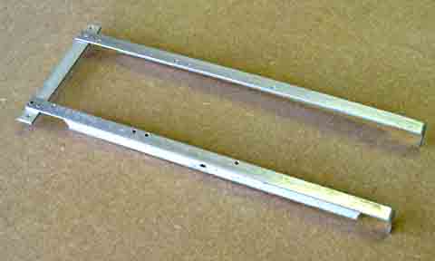
I needed to tackle all the miscellaneous mounting tasks required for the many electronics units, the controller cooling system, the power brake vacuum supply, the motor speed sensor, etc. I chose these tasks next. Main Electronics Board Hinges First I wanted to finalize the location and mounting technique for the main electronics mounting board. I did several paper templates, and after firming up the design, I made a stiff cardboard one. I determined the height I needed for proper clearance both above and below this board. I did a rough design of the hinges. These all allowed me to determine exactly where I needed to mount the hinges. For a design I chose to have a "double shear" style of hinge. A simple bolted joint between two members, one fixed and the other movable, would have worked, but not been nearly as stable. I also decided to not allow a threaded bolt to be the pivot, with the threads acting as part of the pivot. My solution here was to use steel tubes as the pivots. These will be held in place using a smaller bolt through the center. The fixed hinges were made by welding a 1 inch angle to
the web of a
1 1/2 inch angle, leaving a gap of 0.140 between them. The
outlines
were then cut to the desired size and shape.
I mounted the cardboard template to my hinges and can
lift the assembly
just as I will the final assembly. I plan to mount packaged
assemblies
such as the controller and its interface, and the DC to DC converter to
the top of the board, and my contactors, shunt, and fast acting fuse on
the bottom.
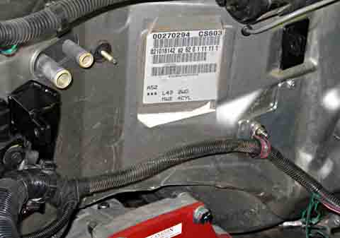
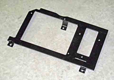
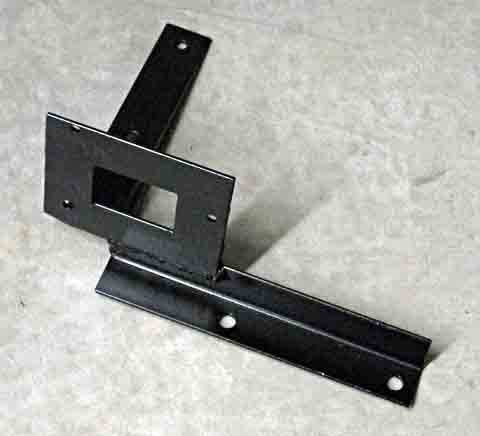
Computer and Cooling Pump Mounting The original engine computer assembly is still going to be required for a couple of tasks on my electric truck. It was originally mounted on the radiator overflow bottle on the right front fender well. I removed the bottle, which left the computer un-mounted. I decided to make a frame to mount the computer and the
vacuum pump,
both of which would fit after removing the bottle and moving the
computer
back a little.
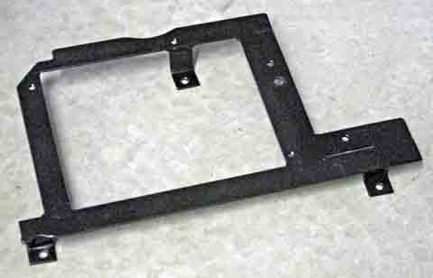
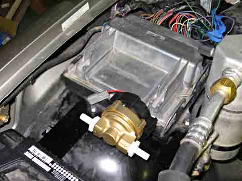
After completing the frame, which mounts on the studs which mounted the overflow bottle, I started thinking about what the effect of the vacuum pump vibration would be on the computer. I decided to move the vacuum pump and mount something else on this frame with the computer. I decided to mount the coolant circulating pump here, as it should run very smoothly. This pump keeps the coolant flowing through the Zilla controller and the radiator. To make the change, I cut off a corner of the bracket
and added a mounting
hole.
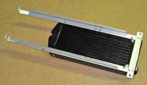
Controller Radiator Mounting The controller cooling radiator and reservoir was
next. I found
some surplus aluminum extrusions in a modified angle
configuration.
I riveted a cross piece at the top to give access to mounting screws,
and
bent the bottom to mount on a lower pan.
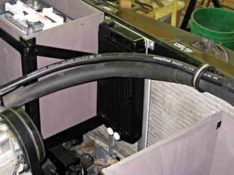
The final mounting location is behind the air
conditioning condenser.
Cooling air will pass first through the condenser then through the
radiator.
I can mount up to two fans on the radiator if needed.
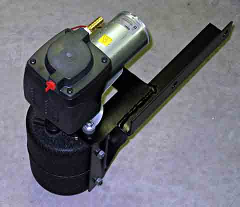
Vacuum Pump and Reservoir Mounting In looking for a better location for the vacuum pump, I
decided to mount
it below the electronics board on the transmission bell
housing.
I discovered that there was also room for mounting the vacuum storage
reservoir
just below it. This is a far better location than the
original one,
as it puts all the equipment very close to the brake master cylinder,
and
should be less likely to radiate the sound as it would have on the
sheet
metal fender..
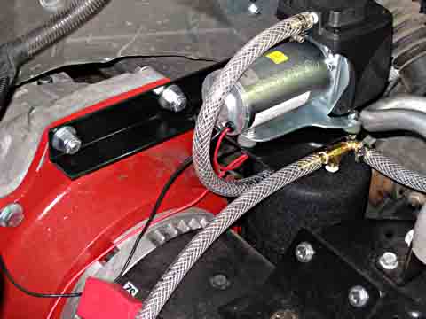
After assembling all the components, I connected the
hoses between the
pump, reservoir, and the power brakes. There is one extra
hose that
is currently connected to the vacuum gage, but will eventually connect
to the other vacuum operated devices, namely the heater and air
conditioning
baffles.
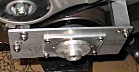
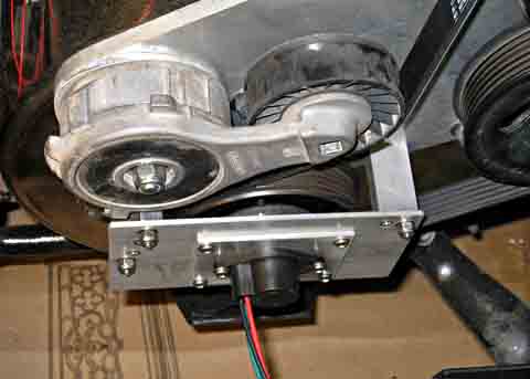
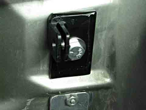
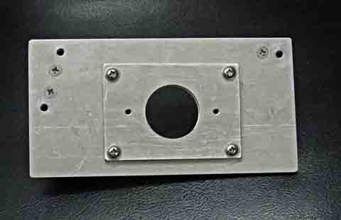
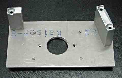
Motor Speed Sensor Mounting My next project was to mount the motor speed sensor. This is a round magnet that mounts on the motor shaft surrounded by a sensor housing. Since the drive pulley for the air conditioning and the power steering is already mounted on this shaft, I need to extend the shaft and make a bracket to hold the sensor beyond the pulley. I decided to use a flat plate mounted on spacer blocks. The alignment between the shaft and the sensor housing is critical. There is about 0.050 total clearance between the magnet and the housing. This means that a .025 misalignment will cause the magnet to scrape the housing. My tolerances are much tighter. I figure that I should allow a maximum of .010 misalignment. My design was a two configuration one. I
originally designed it
to have a base plate with a secondary plate screwed to it.
This secondary
plate could be adjusted to provide my exact alignment. I then
decided
to first try a single plate that would mount the sensor directly,
relying
strictly on fabrication tolerances to hold the alignment.
This is
risky as there are many tolerance that add up to the total
misalignment
If the results of this were not accurate enough, I would then make the
secondary "floating" plate.
I had previously provided 3 threaded mounting holes in
the air conditioning/power
steering base plate for mounting this assembly. I decided to
use
threaded rod, held by lock nuts to provide studs. This made
assembly
easy, and assured a full thread engagement in the base plate.
After
completing the basic plate, I installed it and measured the alignment
between
the hole and the motor shaft. I was almost .025
off! This amount
would either just drag the magnet, or just miss dragging it.
I need
to make the floating plate.
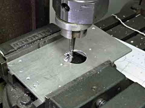
I made the small plate, boring the alignment hold in it
as I had in
the main plate initially. I also drilled and tapped the
sensor mounting
holes in this plate as well as providing the 4 holes to mount it to the
main plate. I added matching threaded holes in the main plate
and
drilled out the old sensor mounting holes to be clearance holes for the
ends of the screws.
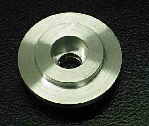
To be able to mount the magnet, I had to make a spacer
to extend the
motor shaft the amount needed to align the magnet with the sensor
body.
I made an aluminum spacer with a well centered .250 diameter
hole.
This spacer had to be accurate, as it is an integral part of the
alignment
system.
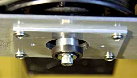
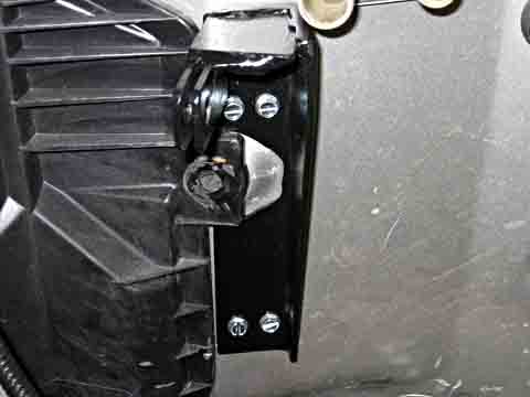
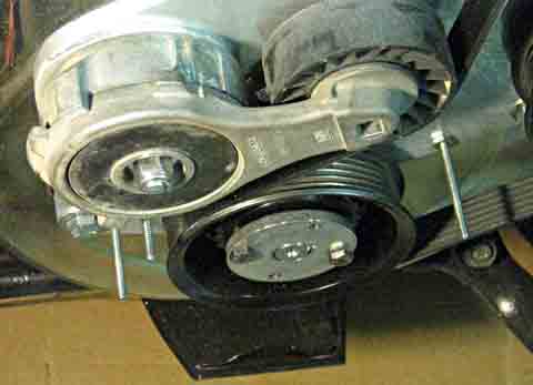
To align the floating plate, I bolted the extension shaft to the motor shaft without the magnet. I then used a specially made alignment tool that slid over the extension shaft and had a diameter that fit the sensor alignment hole. Once the tool was in place, assuring the sensor mounting hole was accurately aligned with the motor shaft, I tightened the 4 screws to lock the plate in its properly aligned position. I then remounted the shaft extension with the magnet in
place.
Now that the magnet is mounted, I am ready to mount the
sensor housing.
The alignment should be within a couple thousandths of an inch.
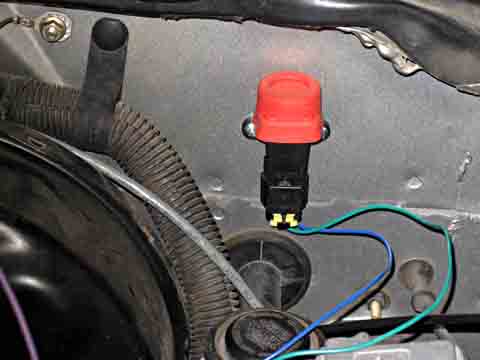
Fastening the sensor housing in place completed the installation. If I need to change the serpentine belt some time in the future, I only need to remove the 3 nuts holding the assembly to the studs. When done, I can slide the assembly back over the studs and tighten it. The alignment will not be affected. Inertia Switch Mounting Installing the inertia switch completed the mounting of
all the loose
items under the hood.
This is my progress through September 30, 2008
To go to the next section, click here.
|
||||||||||||||||||||||||||||||||||||||||||||||
|
Dick
Mason, Prescott, AZ 9/21/08
|
 .
.