Refurbishing a 1976 Sol Terminal Computer - July 2024
Overview:
I recently became the proud new owner of a 1976 vintage, Sol Terminal Computer system, also known as the Sol-20. The pieces I received were:
- The primary computer, consisting of a
keyboard, a power supply, a motherboard, and several S-100 plug-in
boards in a cabinet.
- A
dual 5 1/4 inch disk drive system, with a built in power supply, basic
support electronics, and cabinet, along with an S-100 controller board.
- A small TV which has been converted to include a composite video input for use as a monitor. This is not a Sol component.
As this system is about 48 years old, I had no idea what to expect.
This article is being written as the work is accomplished. What you read represents the status as I know it at the time that section was written, and obviously this will change often as work progresses.
Enjoy traveling with me through this adventure!
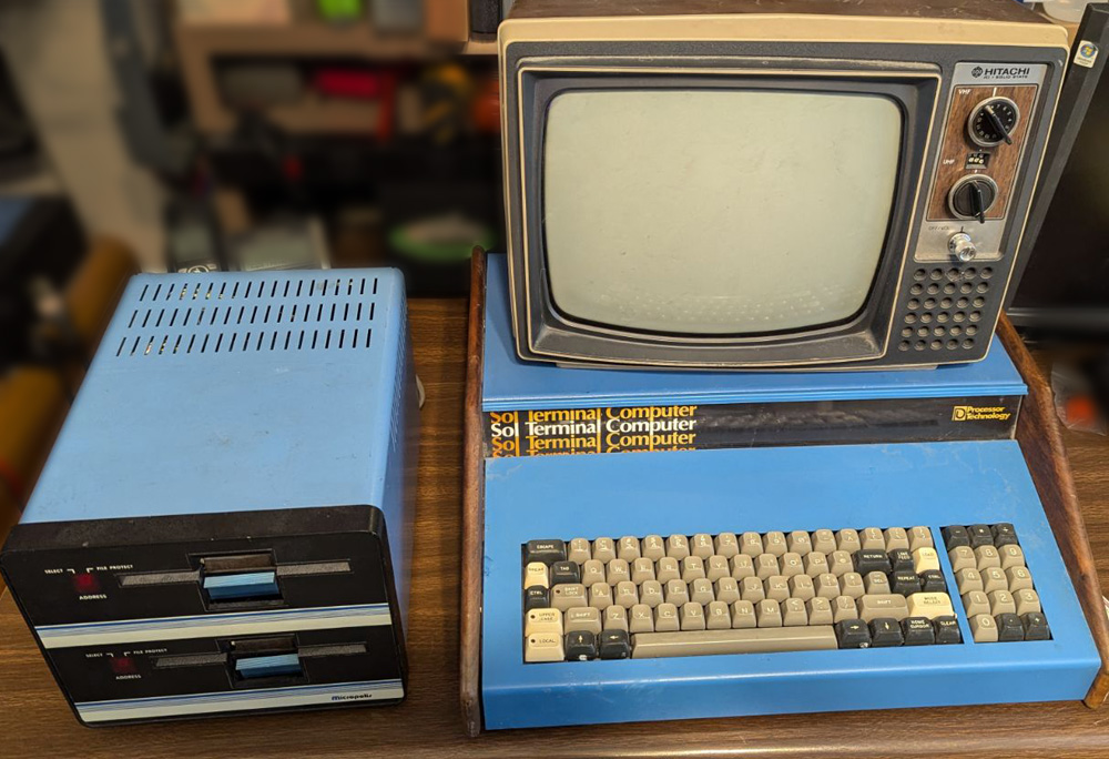
This is the Sol system. The word "Terminal" was to indicate that this can be used either as a stand alone computer, or as a
remote computer terminal to create a work station, often for a central mainframe computer.
After an initial inspection, I powered up the computer and I got the prompt on the display, which is an excellent sign. The bad news is that after trying all the keys on the keyboard, only the 1 and 6 of the right hand key pad worked, but the fact that any keys work, shows that a good portion of the electronics involved is working.
Keyboard:
Somewhere in its past history, something gooey and sticky was spilled on the keyboard. When I first tried it, a block of about a dozen keys would not press. If I pressed hard enough, I found I could press all of them together as a single unit. I managed to cut the "glue" bonds between keys and did some judicious washing with water and removed most of the visible hardened goo, I have no idea what it is, but it is water soluble. After testing every key, the good news is the 1 and 6 still work. The bad news is the 1 and 6 are still the only ones working.
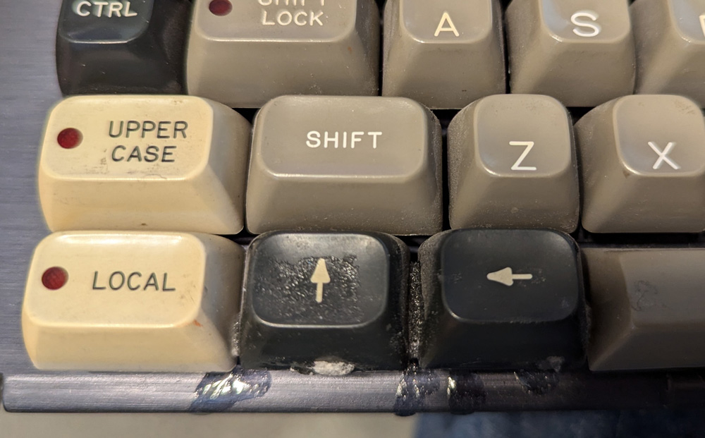
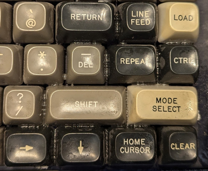
Two areas of the keyboard had the unknown goo spilled on them, several keys in the lower left corner, and about
a dozen keys in the lower right. The sticky bond can be easily seen here.
A brief description of how the keys work is that each one has a keycap
attached to a plastic spring loaded plunger. On the bottom of the
plunger there is a disk of very soft foam with a silver disk on the
bottom of that. This disk is thin mylar with a metal layer on the TOP SIDE.
When you press the key, the disk is lowered into physical (but not electrical) contact with a
split circle on the printed circuit board below, and pressed firmly by slightly compressing the foam. There is no
electrical contact, but the top side metal comes very close to the
contacts, increasing the capacitance. Through the magic of
electronics, this registers the key stroke.
Over the last 48 years, the foam has pretty much disintegrated. When I disassembled the keyboard, there were many disks on the keys where they belong, but also many just scattered around with some stuck to the circuit board, probably making the logic believe those keys were continually pressed.
This keyboard definitely needs a total overhaul!
After drying from the initial cleaning, a number of the contaminated keys would stick in the up position, then break free given enough pressure. They would then physically operate normally until allowed to sit a while, when they would again stick .
I removed all those keys from the mounting frame and soaked them in warm water, pressing and releasing the keys during the process. This seemed to clean them adequately.
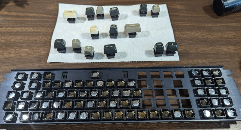
This shows the sad state of the mylar disks and the foam. About half the disks fell out of place as soon
as I removed the keys from the circuit board. Many were stuck to the circuits.
On the paper towel are the keys I removed to soak separately.

Each key has a split circle pad which is capacitively actuated by bringing the insulated mylar metal
into close proximity (a thousandth of an inch or two). I gained some confidence in the electronics
by "typing" with my fingers on the circles. All the positions seem to work!
After I removed all the keys from the circuit
board, I could fool the electronics by touching the split circles
with my finger and all the key positions seemed to work! Hooray!
Keytronic, the maker of these keys was formed several years before this computer was made, and is still in business today. They carried a rebuild kit for these keys until about 2001. Fortunately a small online business, TexElec, has started making replacement foam disks with attached metalized mylar (I will call them foam/foil) replacements, and I just ordered a kit of 105 pieces from them.
Most of this line of keys have several small "claw" clips that hold the foam/foil pieces in place, allowing them to just clip or un-clip to install or remove them. However, the very early ones such as mine use a small disk of strong adhesive film to hold them. This causes several problems for me trying to renew this keyboard. Now FINALLY complete, the existing adhesive was quite a project to remove! It will also be quite a bit of extra work to attach adhesive to the new pads, trim it to size, and then carefully position the pad to press into place. And this must be done for 85 separate keys!
At my request, Sara of TexElec suggested several adhesive options. I selected a 4 by 8 inch sheet of 3M 300lse adhesive transfer tape, and ordered it from Amazon.

I was very happy to finish removing the old adhesive disks from the plastic plungers! It was a tedious process of scraping the rotten
foam off, then sliding the adhesive using a 1/4 inch chisel and trying to grab it with small needle nose pliers to lift it off. Sometimes
the adhesive disk would just lift off cleanly the first time, but, of course most of the adhesive disks tore multiple times before
I could successfully remove them.


To aid in removing the key switches from the metal frame, I 3D printed a tool. I slide this tool over the body and being a snug fit,
it depresses the two tabs which lock the housing into the metal frame. With the tool, slide it on, press the switch out.
The right shows the detail of the plastic plunger. The foam/foil disk will glue in here between the two side guides, and must be
manually positioned in the other direction to not hang up on the housing, and to stay in line with the circuit pads below.
After the selective cleaning of
keys, I
re-assembled them into the frame. A couple days later I
tried all the keys for smoothness. I found a number that had an
annoying, but harmless slight initial stickiness. I decided that
if I am going to do any more cleaning, it needed to be before I install
the foam/foil pieces, so I removed 84 of the keys from the frame (the
space bar worked very smoothly, and is a real pain to remove and
re-install, so I left it.), and in 3
batches ran them through my ultrasonic cleaner. This seems to
have totally eliminated any remaining stickiness.

I ran each batch of keys for a few minutes in warm water, then changed to clean water and ran them again. It seemed to work quite well.
The first tool I made to simplify my life, the tool to remove keys from the metal frame, has already been shown, and presumably I will no longer need it. It made a tedious job easy.
In analyzing the process needed to refurbish the keyboard, I identified a couple places where an additional tool or two would make the process faster and better. As I worked it out, the assembly process will look something like this:
- Remove the protective sheet from one side of the adhesive
- Stick 85 (plus several spares) of the new foam/foil pieces to the adhesive
- Cut the adhesive to separate the foam/foil pieces, then for each one do steps 4 through 7:
- Fit a piece of paper with a 7/16 hole over the foam/foil to stick to the adhesive which extends past its outline
- Trim the excess adhesive
- Remove the remaining protective cover sheet (now a disk) from one foam/foil piece
- Place the adhesive coated foam/foil onto the plastic plunger on the switch bottom - carefully align it before the adhesive touches anything and sticks
- Replace all the keys into the metal frame and screw the frame to the circuit board.
- Say a short prayer, then test the keyboard

This punch is my attempt to make a precision hole and die type punch. It will be useful in punching many
holes in paper to protect from the tacky adhesive which extends past the outline of the foam/foil. Then
the foam/foil is actually placed into the bottom hole of the punch with the protected adhesive facing up,
and punched out of the excess adhesive. The paper placed on the excess adhesive keeps it from
sticking to the punch.
Initially my drill rod punch was a little too loose in the reamed guide hole, so I cut a slot into the hole and
pulled it just the slightest bit together with a pair of screws. This allowed me to adjust it to keep the rod free to
move without any appreciable play.
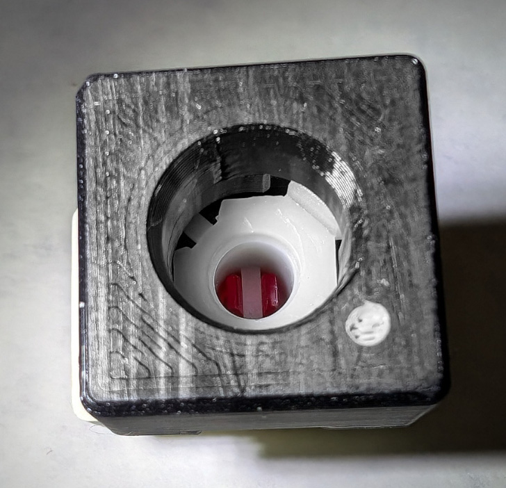

The assembly jig slides over the bottom of the key, with the white dot in line with the hole in the key body. It allows me to place the foam/foil
with open adhesive on the bottom in the exact location I need it. There is a guide tube going down to the plunger bottom. The tube is notched
around the existing guides. Hopefully I will be able to drop the foam/foil into the hole and press it in place with a short dowel. I will know
soon, as the repair kit is due tomorrow (as I write this).
I just received the foam/foils from TexElec, and they look beautiful! They are about ten thousandths larger in diameter than I expected, so I reprinted my insertion tool with a slightly larger hole, as the original tool wrinkled the mylar as it passed through the alignment tube. I also made another tool which allows me to fully seat the adhesive layer.
Even with the enlarged hole, I still initially had a problem feeding the foam/foils down, as the adhesive on the edges tended to stick to the tube wall. I then changed my way of operating: I fed the foam/foils up from the bottom, never allowing the adhesive to contact the tool. This worked very well and actually sped up the process while also improving the quality.
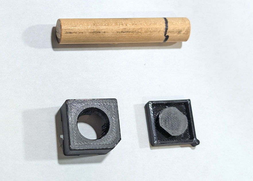
I reprinted the insertion tool with a slightly larger center hole. I also substituted a chopped corner for the white dot.
The dowel has a smooth, flat end to use in pressing the foam/foil into place.
The lower right shows the tool I made to make sure the foam is fully adhered to the bottom of the plunger.
Placing the key in the recessed square and pressing the key cap applies enough pressure to fully set the adhesive,
and the pressure platen is larger than the foam/foil, minimizing any distortion to the mylar.
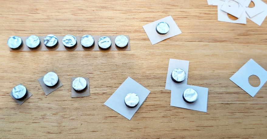
To start the assembly process, the adhesive's top protective sheet is lifted and laid back to expose a couple inches of adhesive, and
the foam/foils are stuck to it. Seven pieces can be placed along the 4 inch edge, and I process 2 rows at a time. After placing
the foam/foils, I cut them apart into single units. The open adhesive is vicious! It seems that for every unit I pick up, I find two
more hanging from my hand or arm. (a slight exaggeration!) Placing the punched paper over the foam/foils and sticking
them to the adhesive totally solves this problem, as well as keeping the excess adhesive from sticking to the punch.
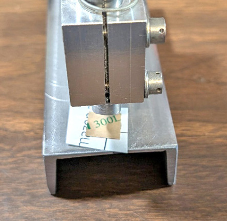
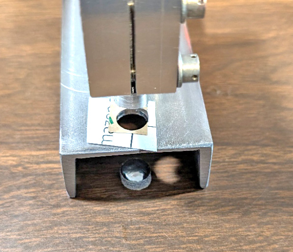
To trim the adhesive and the protective paper, the foam/foil is placed into the die hole and the punch is operated. This
punches the finished unit out the bottom, ready to be placed into the key.
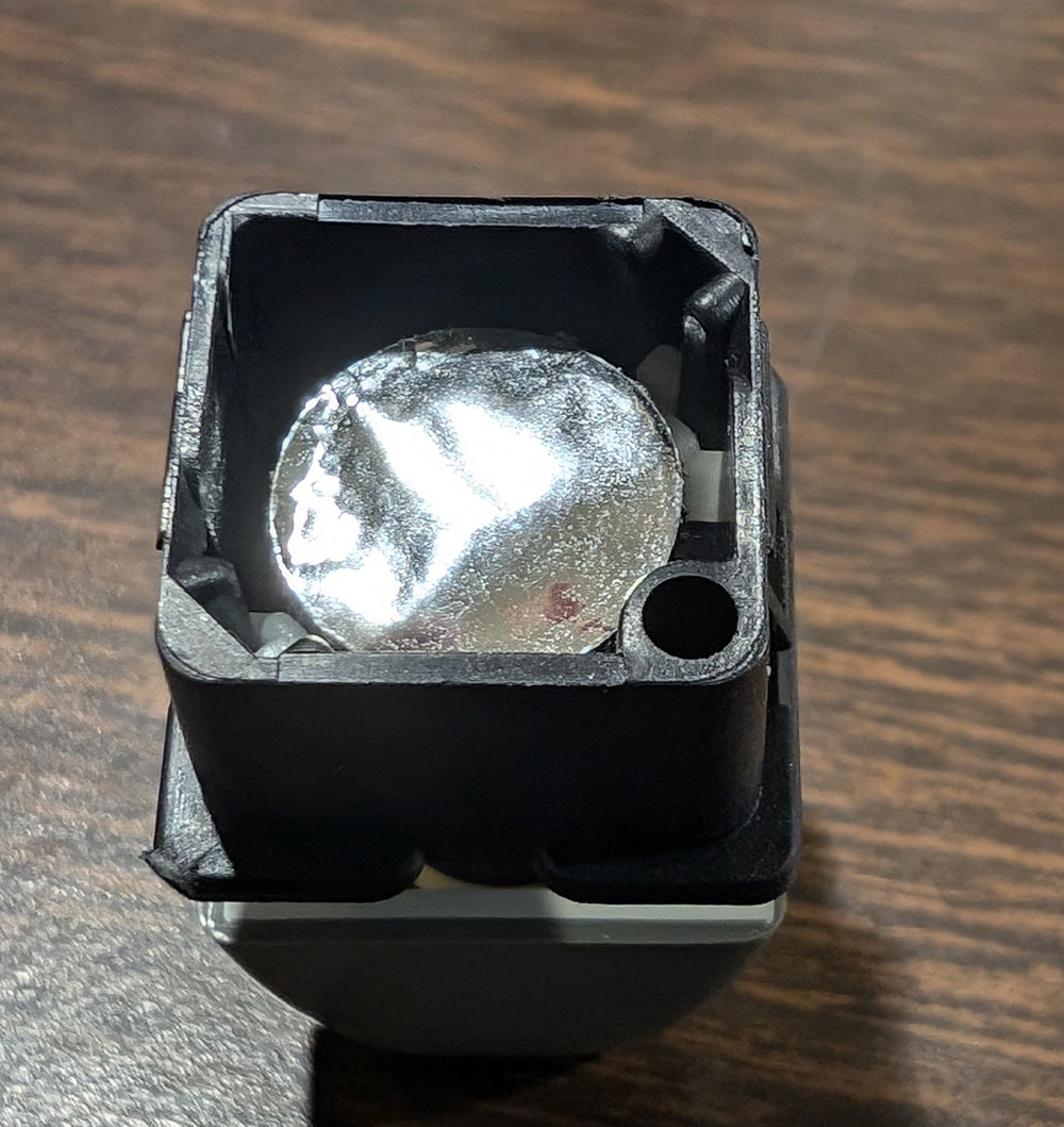
The hardest single step is removing the remaining protective disk to expose the other side of
the adhesive film. I found that a fine pointed pick worked best (better than a new Xacto blade).
By lifting one edge of the disk, I could peel the balance off, then tap it back lightly to the
adhesive, to use as a handle to move the foam/foil into the placement jig. Then it is all pressed
down lightly with the dowel, the key is placed into the new seating tool, and firmly pressed down.
The key is now ready to snap into the metal frame.
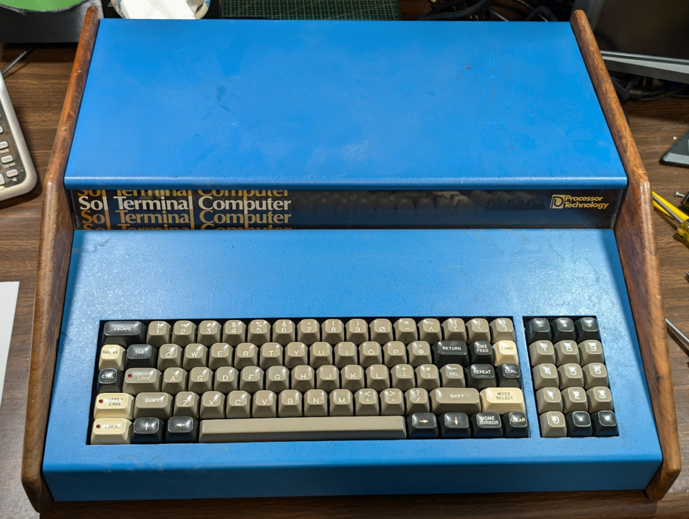
Once the frame was again fully populated with keys it was screwed to the circuit board and replaced into the computer. At first I was
worried about some keys with wrinkled or creased mylar (a condition which I saw less often as I got practice). I feared these keys
might be less sensitive, but every key prints prior to the key hitting bottom with no discernible difference between them.
All the keys actuate smoothly, with no detectable initial sticking, and they all work! I'll try my best to keep any sticky goo away from them!
I'll bet that as this computer was growing up, it never imagined it would someday display on a 27 inch flat screen display! This was
possible with a composite video to HDMI adapter I had left from a previous project, and the extra display I keep in the corner to
occasionally use as a 3rd monitor on my main computer, or for projects like this!
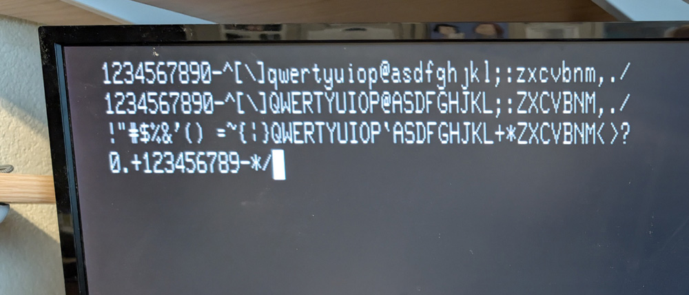
All the proper characters display, with the top line showing the normal main keys, the second line was with the UPPER CASE key active,
and the third line with the SHIFT LOCK key active. Upper Case will capitalize all the letter keys, but not the number and symbol keys.
The Shift Lock gives the upper case letters and the upper character of all the other keys. The last line is the numeric keypad which is not
affected by either of the shift modifier keys.
I have actually been making the
computer do some simple things. With the built in firmware I can
load data, one byte at a time into a selected area of memory using the
ENter command, (In this mode the several commands available need only
the first two letters to operate.) I can also view any range of
memory using the DUmp command. Using these 2 commands I have been
able to determine the memory range of each of the 3 memory boards in
the system. There is a whopping 48 kilobytes of Random Access
Memory (RAM) in this system.
Other than the 3 RAM boards, the only other added board is the disk controller. I am hoping that the fairly small amount of fixed Read Only Memory (ROM) I found on this board is sufficient to run the disks without having to load any other software first!
Now that I know more about what I am dealing with, the largest challenge ahead is finding some software for this machine and figuring how to initially load it so I can then use the diskettes to save and restore the programs (hopefully!). Time will tell if I am up to this significant challenge!
I have been able to do enough with the computer to feel confident that most parts of it seem to be working correctly! This is a great relief! I am hoping to be able to do something a little more exciting with this system than just running memory dumps! (Although the first memory dump I ran was VERY exciting! aka "It's alive!")
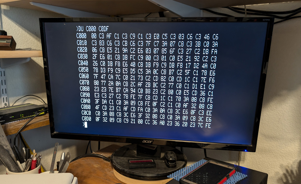
A typical memory dump.
Programs and Storage:
Now that I have the computer hardware repaired and running (mainly by overhauling the keyboard), I can start investigating what needs to be done to to load programs into this system. There are a number of programs available to me on several websites memorializing the Sol and supporting folks (like me) who are resurrecting these machines. At this time I have no idea what steps are going to be required. I will start with trying to establish a working serial connection between the Sol and a Windows computer. I will use a Dell Inspiron 8100 Laptop I purchased around 2001. It is the newest computer I have which still has a factory serial port. In an effort to try and work on only a single unknown at a time, I wanted to start with a factory serial port, as I have previously had problems using USB to serial conversion cables. When it all works with this system, I will try moving to a modern computer using a plug-in serial port.
Thanks to the generosity of many hobbyists who have scanned manuals, uploaded software, and provided the documents to support the entire system, I am well provided with technical information about this system. I started by studying the connections and the dip switch settings needed to configure the serial port and finding the needed cables. Once I put all this together, I plugged the Sol into the Dell, opened a terminal program on the Dell, and once I changed the mode of the Sol to a terminal, I had serial communication. What I typed on the Sol displayed on the Dell and vice-versa! WOW! I have never configured a serial connection that easily!

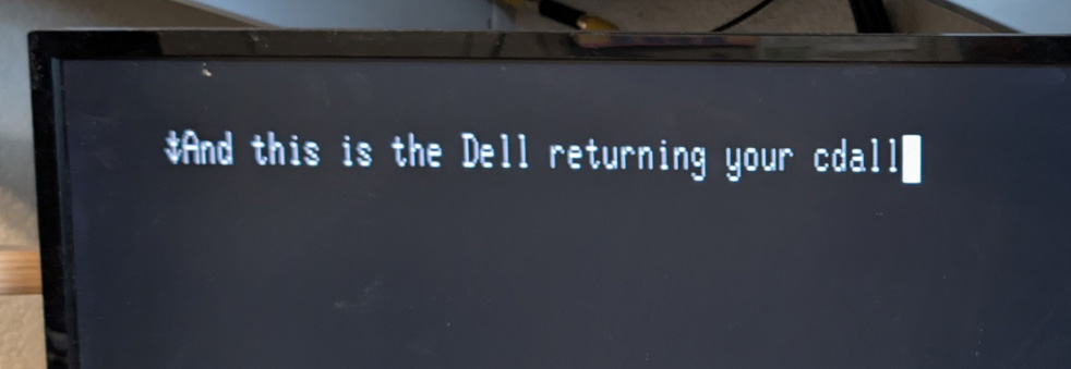
I was amazed how quickly I was able to get a successful connection between the two computers, remembering the difficulties I used
to have anytime I had to configure a serial port! This is my first "conversation", including initially just running my fingers across
the keys and my typos.
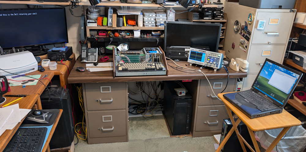
The setup for this test took pretty much my whole office! The Sol display is to the left, then the coverless Sol,
my oscilloscope for monitoring the signals from each computer, and my 20+ year old laptop.
My office often is not particularly neat and clean, but this is ridiculous!
I then looked at the formatting of the on-line programs and they all looked very much like the memory dumps I can view on the Sol. Each line starts with a *hexadecimal (hex) address and continues with 16 single byte hex values. I found a "Transfer" menu on the Dell's terminal program and after a couple false starts, clicked on "transfer a text file" and son-of-a-gun, it loaded! I had to initially issue a command to the Sol to input from the serial port, and a couple of minor details to make it all work, but it does work! I quickly wrote down all the required steps and have subsequently loaded many files (or more accurately, a couple of files many times), with this routine. I started with a fairly safe slow baud rate of 1200 bits per second, which including overhead (i.e. two printable characters for each byte, plus the 4 characters addressing each line, 16 spaces and a carriage return per line - yes, each of these is sent separately), their version of BASIC took about 3 1/2 minutes to load. This amounts to just over 30 bytes per second. The BASIC program is 6582 bytes long and occupies locations from 0 to 19B6 hex. This is using about 13.5% of the memory.
After determining that this setup worked reliably, I tried raising the speed. The first time I tried 2400 baud it failed. In the terminal program on the Dell, there is a place to specify adding delays after each character and/or after each line. I added a 25 millisecond delay after each line, and 2400 baud worked fine, and loaded the BASIC program in about 2 minutes. Further trials at 9600 baud still only needed a 25ms. delay, and now it loads BASIC in about 30 seconds. I am pleased.
A New Control Computer:
I just solved a problem that has been causing a significant nuisance! I checked the manual for my main machine's motherboard and found that it supports a native serial port. It took me less than an hour to fabricate a cable that plugs into the motherboard and ends in a DB-9 serial connector. This connector mounts in a board slot closing plate that installs on the rear of the computer. I found a terminal program called CoolTerm that runs under Windows 11 to replace the Hyper-terminal program which will not run with W11.
I can now do all my uploading and downloading to the Sol using my primary computer, and have put away my turn-of-the-century laptop! I have also developed a workable system for saving and loading BASIC programs using my PC. The only built-in system for this uses the cassettes. Unless I get a quality tape system which will work reliably with that interface, I cannot use their primary system.
My system consists of moving files back and forth between the Sol and my PC. The PC end merely sends, or receives and captures the data that make up the files.
To save a program, the Sol is set to output to the serial port and the PC to receive a file from the serial port, then I list the file. This transfers the file, including its line numbers, intact to the PC except for an extra line. The LIST command activates the data dump, but also transfers to the PC and should be edited out.
To restore an existing program to the Sol, I set the Sol to input from the serial port and I simply send the file to it. The Sol receives it and treats it as though it is being typed in. I do like to add one line to the end of the program to set the input to the Sol back to its keyboard, otherwise I need to reset the Sol and start running the already loaded BASIC. I also need to add to the delay time after each line to allow time for BASIC to process the statements. I don't want that much delay when loading the main programs into the Sol, as it takes much longer to load, due to the many, many lines involved, so I make one profile for the Sol, with the short line delay, and another for BASIC with a long delay. Once I enter BASIC I change profiles to use until I exit back to Sol.
These procedures are a little inconvenient, but much better than not being able to save and load the BASIC programs!
It is really great to be able to do all this now from my main computer!
Program Storage:
Modern computers mostly use SSDs, hard drives, and thumb drives for storing programs and data. The Sol used cassette tapes! As home computer technology progressed many of the early systems added floppy disk capabilities, this Sol included.
I am interested in getting this system operational to the level it had when it left the factory. Even though I received it with a pair of 5 1/4 inch floppy drives and a controller, I am not planning on trying to implement them. Doing so would include having to locate an available disk operating system like CP/M or PTDOS (Processor Technologies own operating system), and installing and configuring it. I would then have to integrate these particular drives to that operating system. Someone has already done that with this computer, but all the software and configuration information was lost somewhere along the way. I received no documentation or software of any kind with this system, and have already spent far too much time getting it to where it is.
Back in the days when my then current system used cassette tapes for storage, I had a pair of low cost, but excellent recorders, which I modified somewhat for usability and convenience. See my discussion of my early computer days by clicking HERE. I don't recall what I did with these recorders, but it is a certainty that I no longer have them.
Looking through Amazon and Ebay, I was surprised how many models of these desktop recorders are still available. I was also very disappointed to see that almost none of them still have a tape counter. A tape counter allows you to have a number of different programs on a single tape and to be able to move directly to a desired program. I then looked on Craigslist and found one person with a couple of these machines in the next town from here. He was also coming to Prescott the next day for an appointment and we agreed to meet at a local parking lot. His ads indicated that both machines had tape counters, so I picked the one with the most suitable connections for him to bring. Unfortunately, he had mixed up a couple photos between the two ads and the machine I chose did NOT have a tape counter. After a messy couple of days where I switched machines with him, only to find out the one with the counter was faulty, then switching back, I had a machine. I figured for what I have to do, I can get along without a counter. After using it a bit, even with the very limited requirements, I found I do NEED a counter. Another project in the queue?
|
For reference:
1024 bytes (or characters) is a kilobyte. 1024 kilobytes is a megabyte; 1024 megabytes is a
gigabyte. Most modern personal computers contain between 4 and 32
gigabytes of RAM, which is from almost 100,000 to 700,000 times as much
as this computer, which still managed to do quite a bit of work in its
day!
|
Other than the 3 RAM boards, the only other added board is the disk controller. I am hoping that the fairly small amount of fixed Read Only Memory (ROM) I found on this board is sufficient to run the disks without having to load any other software first!
Now that I know more about what I am dealing with, the largest challenge ahead is finding some software for this machine and figuring how to initially load it so I can then use the diskettes to save and restore the programs (hopefully!). Time will tell if I am up to this significant challenge!
I have been able to do enough with the computer to feel confident that most parts of it seem to be working correctly! This is a great relief! I am hoping to be able to do something a little more exciting with this system than just running memory dumps! (Although the first memory dump I ran was VERY exciting! aka "It's alive!")

A typical memory dump.
Now that I have the computer hardware repaired and running (mainly by overhauling the keyboard), I can start investigating what needs to be done to to load programs into this system. There are a number of programs available to me on several websites memorializing the Sol and supporting folks (like me) who are resurrecting these machines. At this time I have no idea what steps are going to be required. I will start with trying to establish a working serial connection between the Sol and a Windows computer. I will use a Dell Inspiron 8100 Laptop I purchased around 2001. It is the newest computer I have which still has a factory serial port. In an effort to try and work on only a single unknown at a time, I wanted to start with a factory serial port, as I have previously had problems using USB to serial conversion cables. When it all works with this system, I will try moving to a modern computer using a plug-in serial port.
Thanks to the generosity of many hobbyists who have scanned manuals, uploaded software, and provided the documents to support the entire system, I am well provided with technical information about this system. I started by studying the connections and the dip switch settings needed to configure the serial port and finding the needed cables. Once I put all this together, I plugged the Sol into the Dell, opened a terminal program on the Dell, and once I changed the mode of the Sol to a terminal, I had serial communication. What I typed on the Sol displayed on the Dell and vice-versa! WOW! I have never configured a serial connection that easily!


I was amazed how quickly I was able to get a successful connection between the two computers, remembering the difficulties I used
to have anytime I had to configure a serial port! This is my first "conversation", including initially just running my fingers across
the keys and my typos.

The setup for this test took pretty much my whole office! The Sol display is to the left, then the coverless Sol,
my oscilloscope for monitoring the signals from each computer, and my 20+ year old laptop.
My office often is not particularly neat and clean, but this is ridiculous!
I then looked at the formatting of the on-line programs and they all looked very much like the memory dumps I can view on the Sol. Each line starts with a *hexadecimal (hex) address and continues with 16 single byte hex values. I found a "Transfer" menu on the Dell's terminal program and after a couple false starts, clicked on "transfer a text file" and son-of-a-gun, it loaded! I had to initially issue a command to the Sol to input from the serial port, and a couple of minor details to make it all work, but it does work! I quickly wrote down all the required steps and have subsequently loaded many files (or more accurately, a couple of files many times), with this routine. I started with a fairly safe slow baud rate of 1200 bits per second, which including overhead (i.e. two printable characters for each byte, plus the 4 characters addressing each line, 16 spaces and a carriage return per line - yes, each of these is sent separately), their version of BASIC took about 3 1/2 minutes to load. This amounts to just over 30 bytes per second. The BASIC program is 6582 bytes long and occupies locations from 0 to 19B6 hex. This is using about 13.5% of the memory.
| *Hexadecimal (or hex for brevity): Hexadecimal representations of numeric values are very similar to our base 10 decimal system, except they are a base 16 system. Instead of 10 different numbers put together to represent any value, there are 16. They use the numbers 0 through 9 and then the letters A through F to describe the 16 different numbers involved. Hex is used because it "comes out even" when used for the binary values in a computer. For instance, a 2 digit hex number can describe any of the 256 values of a byte, and a 4 character one describes all the 65536 values of the addresses used in this early type computer. If you don't understand how all this works, it's OK, you don't need to. Just be aware that it looks different from our standard decimal system and works much better with computers. |
After determining that this setup worked reliably, I tried raising the speed. The first time I tried 2400 baud it failed. In the terminal program on the Dell, there is a place to specify adding delays after each character and/or after each line. I added a 25 millisecond delay after each line, and 2400 baud worked fine, and loaded the BASIC program in about 2 minutes. Further trials at 9600 baud still only needed a 25ms. delay, and now it loads BASIC in about 30 seconds. I am pleased.
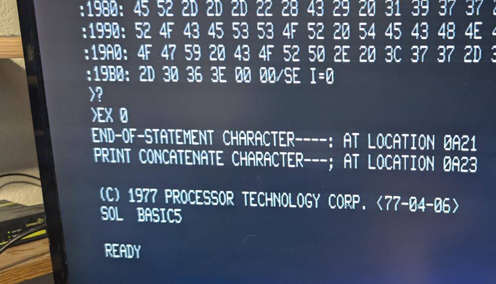

- After loading BASIC, I was thrilled when it actually ran! I quickly wrote a simple program displaying the somewhat
- modified but pretty much obligatory first program of Hello World and included a simple math calculation.
A New Control Computer:
I just solved a problem that has been causing a significant nuisance! I checked the manual for my main machine's motherboard and found that it supports a native serial port. It took me less than an hour to fabricate a cable that plugs into the motherboard and ends in a DB-9 serial connector. This connector mounts in a board slot closing plate that installs on the rear of the computer. I found a terminal program called CoolTerm that runs under Windows 11 to replace the Hyper-terminal program which will not run with W11.
I can now do all my uploading and downloading to the Sol using my primary computer, and have put away my turn-of-the-century laptop! I have also developed a workable system for saving and loading BASIC programs using my PC. The only built-in system for this uses the cassettes. Unless I get a quality tape system which will work reliably with that interface, I cannot use their primary system.
My system consists of moving files back and forth between the Sol and my PC. The PC end merely sends, or receives and captures the data that make up the files.
To save a program, the Sol is set to output to the serial port and the PC to receive a file from the serial port, then I list the file. This transfers the file, including its line numbers, intact to the PC except for an extra line. The LIST command activates the data dump, but also transfers to the PC and should be edited out.
To restore an existing program to the Sol, I set the Sol to input from the serial port and I simply send the file to it. The Sol receives it and treats it as though it is being typed in. I do like to add one line to the end of the program to set the input to the Sol back to its keyboard, otherwise I need to reset the Sol and start running the already loaded BASIC. I also need to add to the delay time after each line to allow time for BASIC to process the statements. I don't want that much delay when loading the main programs into the Sol, as it takes much longer to load, due to the many, many lines involved, so I make one profile for the Sol, with the short line delay, and another for BASIC with a long delay. Once I enter BASIC I change profiles to use until I exit back to Sol.
These procedures are a little inconvenient, but much better than not being able to save and load the BASIC programs!
It is really great to be able to do all this now from my main computer!
Program Storage:
Modern computers mostly use SSDs, hard drives, and thumb drives for storing programs and data. The Sol used cassette tapes! As home computer technology progressed many of the early systems added floppy disk capabilities, this Sol included.
I am interested in getting this system operational to the level it had when it left the factory. Even though I received it with a pair of 5 1/4 inch floppy drives and a controller, I am not planning on trying to implement them. Doing so would include having to locate an available disk operating system like CP/M or PTDOS (Processor Technologies own operating system), and installing and configuring it. I would then have to integrate these particular drives to that operating system. Someone has already done that with this computer, but all the software and configuration information was lost somewhere along the way. I received no documentation or software of any kind with this system, and have already spent far too much time getting it to where it is.
Back in the days when my then current system used cassette tapes for storage, I had a pair of low cost, but excellent recorders, which I modified somewhat for usability and convenience. See my discussion of my early computer days by clicking HERE. I don't recall what I did with these recorders, but it is a certainty that I no longer have them.
Looking through Amazon and Ebay, I was surprised how many models of these desktop recorders are still available. I was also very disappointed to see that almost none of them still have a tape counter. A tape counter allows you to have a number of different programs on a single tape and to be able to move directly to a desired program. I then looked on Craigslist and found one person with a couple of these machines in the next town from here. He was also coming to Prescott the next day for an appointment and we agreed to meet at a local parking lot. His ads indicated that both machines had tape counters, so I picked the one with the most suitable connections for him to bring. Unfortunately, he had mixed up a couple photos between the two ads and the machine I chose did NOT have a tape counter. After a messy couple of days where I switched machines with him, only to find out the one with the counter was faulty, then switching back, I had a machine. I figured for what I have to do, I can get along without a counter. After using it a bit, even with the very limited requirements, I found I do NEED a counter. Another project in the queue?

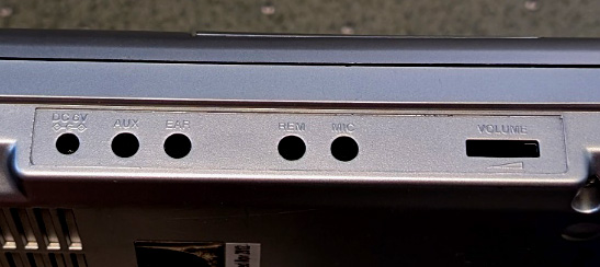
The recorder I bought is pretty much a run-of-the-mill portable Walmart recorder. I liked that this one had an AUX high level input. The MIC inputs
are far too sensitive and would need an external attenuator.

Here I have removed the heavily smoked clear window over the tape. It was almost impossible
to see in before, and now I have access to add a counter.
The cables are for the audio signals in and out, and a remote control line which the computer
uses to start and stop the motor as needed. There is also a power-in connection.
The orange box is a level control I added to the input line to let me determine if this level is critical.
The output line is already controlled by the built in volume control. The level control I added eliminates
my objections to units with only a Mic input, as I can now set the input anywhere between 0 and 100%!
After many, many tries to save a program to this recorder, then restore it to the Sol, I only successfully managed to get it to work twice. After finding settings that worked, I tried it again using exactly the same settings, and it failed! Either the Sol or this recorder is not working the way it needs to be successful.
A note from later: After I learned that the tape I had was the wrong class for this recorder, I obtained a few correct tapes and re-tried some tests. This machine still cannot reliably save and restore programs to the Sol.
To help narrow down the problem, I dragged out my old reel to reel recorder. When I say old, I mean it; this machine uses vacuum tubes, and appears to have been introduced in 1964, making it older than the Sol! I connected it to the Sol in the same manner I had connected the portable unit, and after several tests trying various volume settings I found a fairly wide range where it appeared to be 100% successful! i.e. It went through all the motions, reported the correct file name and size at the conclusion, and did not report any errors.
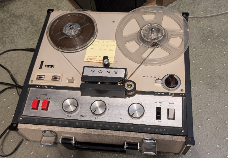
My (very) old Sony reel to reel recorder appears to be 100% successful at saving
and restoring programs from and to the Sol! (and it has a tape counter!)
Spoiler Alert: It was NOT 100% successful!
With the dramatic difference in performance between the 2 machines I decided to look at the waveforms and levels of the signals between them. I monitored the signal the Sol sends to the recorders, which should be the same for both recorders, then I looked at the signals each recorder sends to the Sol. WOW, what a difference! The Sol outputs a square wave with rounded corners. The individual pulses are single width and double width depending on the bit being transmitted. The reel to reel machine outputs pretty much sinusoidal waves with nice rounded contours. The cassette player outputs a signal with very sharp peaks and valleys, nothing like either the original signal or the one from the reel to reel one.
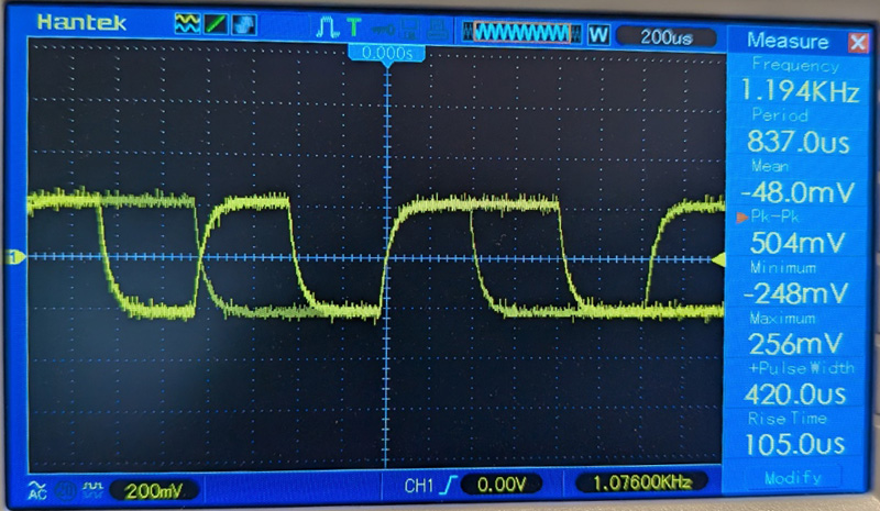
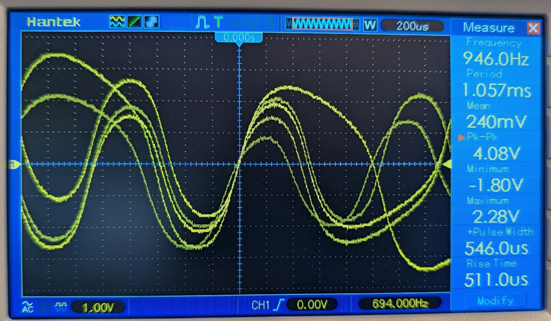
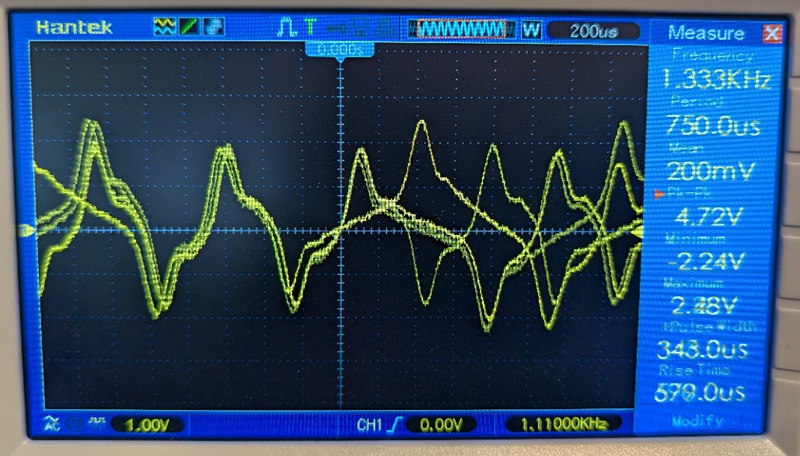
The first picture shows the signal the Sol sends out to be recorded. If you look closely you can see there are narrow and wide pulses (sorry
for the multiple samples). The reel to reel Sony delivers very rounded, rolling hill type signals, while the cassette machine produces
sharp jagged rugged mountain type signals. Neither one is anywhere close to duplicating the input signal, and I guess that makes a difference!
I was quite disappointed with these results! The waveforms produced by the cassette recorder would probably never allow it be reliable, and things like this are probably the reason the computer maker stated (48 years ago) that many cassette players would not work! It turns out that this recorder was a rather cheap one!
However, if the output wave shape is what is keeping it from working, what if I change the wave shape? I can smooth it out using a simple low pass filter, which can be made using one resistor and one capacitor. I had already made a short extension cable for the 3.5mm phone jacks used for all the recorder audio connections. It was a short length of cable with the correct plug on one end. I attached this to a matching jack through 2 short lengths of rigid wire, leaving a length of each non-insulated. This gave me a place to connect my scope probes. I used this cable for my filter by adding a series resistor and a parallel capacitor. After a couple trials and change of values of the components, I had what I was looking for. The output wave shape was now quite smooth and closely resembled the one from the reel to reel machine.
I ran a lengthy series of tests where I would record a known good program using a number of different input volume settings. I then, one by one, loaded them back to the computer. I took the mid-point of the working range and recorded a "master" program. I then loaded this program many times, this time varying the volume of the recorder output and again picked the center of the working range. The outward indications were that it now worked consistently, but it turns out there were still errors within the program.
I think I am probably kidding myself that I can ever make this recorder work consistently. I just need a higher quality machine, which I am not willing to purchase right now. I'll keep my eyes out in the local thrift shops and maybe I can find a suitable unit I can justify.
For the time being, I will use my PC to transfer programs to the Sol. I will not be using the reel to reel recorder which I used to prove the concept, as it is big (and my office is small), it is heavy, and it would have to live on the floor due to unavailable desk or table space. Also, I would need more trials to "tune out" the remaining errors.
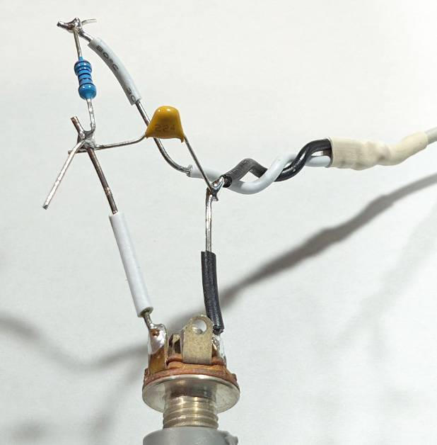
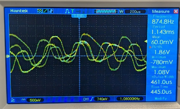
I made a simple Low Pass filter using a resistor and a capacitor to smooth out the waveform put out by the recorder, and after a couple tries
I achieved what I was looking for. Please excuse the temporary air-chassis type wiring done to make construction and changes easy and quick.
I am still worried about the excessive vertical and frequency jitters. The cassette is much worse than the reel to reel in this respect. This
setup made the cassette almost work! It would save a file and then re-load most of it with a few scattered errors. Before the filter I only
had a couple cases where it worked at all.
This recorder is officially a FAILURE!
Other Recorder Trials:
After finally ruling out the small cassette recorder due to its poor performance and the reel to reel as it is just not practical, I started looking around to see what other devices I had that could record sound. I actually found several! I have a small hand held voice recorder designed to record quick verbal notes. I have a VCR/DVD player; my last remaining VCR, which I have kept for the occasional tape I need to view or transfer. I have a device that records video to a thumb drive, and I have a dual cassette JVC home stereo component I just bought for this project at a thrift shop. Of course when I got home and tested it, neither drive moved a tape at all. No surprise there.
I set up and tried both my tiny voice recorder and my video to thumb drive one. Neither of these worked well enough to warrant more extensive tests and were eliminated from the running.
I hesitated, but finally gave in to pulling my VCR off the shelf to give it a try. This was NOT an easy task, but the shelf needed a good deep cleaning anyway! I was pleasantly surprised when the VCR was quite successful at recording and playing back my programs without error! This is really the first solid solution I have found. The reel to reel was close, but still had some errors.


My tiny voice recorder did not work, but my VCR did!
Today as I write this (late August '24) I decided it was time to try repairing my dual cassette machine. I picked this up figuring it would probably require new drive belts. On-line reports state that almost all thrift shop recorders do, so I had picked up a variety pack of replacement belts from Amazon. As I disassembled this dual drive system I started thinking that if I cannot get it back together correctly, at least I got my money's worth in education just digging into the interior! As it turns out, I actually managed to replace all the belts and get it back together - and it now works!
Testing the recorder was much like the previous ones: I had limited, but not total success at first. The big improvement came when I examined the various switches closely. I had initially set them to "Normal", but then I looked at the tape I was using. It said to use the CrO2 setting. I changed that on the recorder and now achieved total success on all runs of 8 or higher for the recording level range. I have now successfully saved several copies of Sol's BASIC program, then the sample program I wrote to check the operation of BASIC itself. It all worked! This machine has now eliminated my growing doubts about the performance of the Sol's cassette software and hardware!
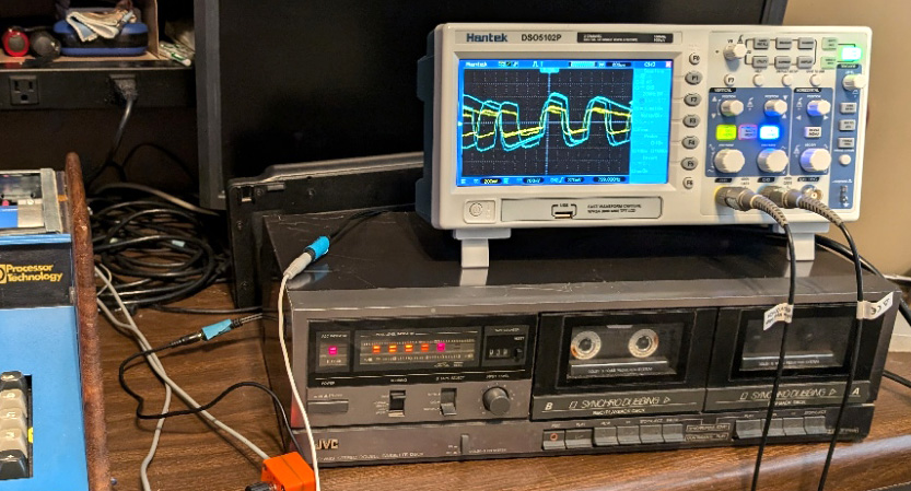
After repairing the JVC dual cassette recorder, I have a system that actually works!
| A quick tape primer: (Things I kinda knew before, but now I truly know) Cassette tape consists of a plastic backing coated with a magnetic substance. There were 4 categories (now 3) of these coatings:
The various types require different electronic settings to properly read and write them. The differences are in the bias level, a high frequency AC voltage added to the audio signal during recording, and the playback frequency equalization, which boosts some frequencies and decreases others. Higher quality cassette machines have either a manual switch or automatic detection to select from Normal, CrO2, or Metal, while simple ones, usually do not even specify, but are mostly only Type I machines. |
I now realize that I used the wrong type tape during all my early tests of the cassette recorder. I had only a Type I recorder and only Type II tapes! I just ordered a 5 pack of " Type I, Normal bias" tapes.
What I should have done long ago! Now that I have proven the cassette interface of the Sol truly works, and that all the problems I have had are the result of incompatible recorders, I bought a "correct" recorder. The Sol manual recommends two different recorders (as of 48 years ago!). One of these was a Radio Shack "Tandy" brand machine. I knew this specific machine would be hard to find, and probably in poor condition if I did find it, but I went to Ebay anyway. Here I found that Tandy had made a series of "Computer Cassette Recorders" specifically targeted at recording computer programs. They made these from about 1976 until 1993. I found one machine listed that was the latest model Tandy had made and made an offer about half what some similar machines were going for. They accepted my offer and I just received it. It is beautiful! I cannot tell if it was ever used. It came in the original box with its foam packing, and all the accessories (except the manual, which I downloaded). It all works, no need to replace the belts.
The important part of this machine is that it works far better than anything else I have tried. It reliably reads and writes without error with anywhere from #2 to #10 on the playback volume control. I am thrilled!


My "Tandy Computer Cassette Recorder" works great and
even has a counter!
Floppy Disk System:
I received this system with a Micropolis dual 5 1/4 inch floppy drive system and controller board. I initially figured that might make my data storage problems easy to solve, but upon looking further into it I realized it would involve extensive study and implementation time and effort. In the end, I decided that trying to implement these drives would be far outside the scope of what I am interested in doing with this system.
There are several obstacles to overcome to get this system working:
- It is old and the drives may or may not work,
- The drives may need alignment or other adjustments (or Heaven forbid, parts!)
- To use the drives requires a disk operating system like CP/M or Sol's PTDOS.
- A disk operating system would need to be configured for the Sol.
- An installed disk operating system would still need to be configured for the drives.
- And the BIGGIE! These drives are "hard sectored" meaning that there is a
hole punched near the center of the disk for each sector in a track (I
believe 16 sectors per track, but possibly 10). Hard sectored diskettes are almost
non-existent today, and for all practical purposes impossible to obtain!*
I have downloaded many manuals, conversion documents, and software for these drives, which should make the installation and configuration of these drives somewhat easier.

These are the Micropolis drives along with their controller board. No cable was provided.
GO BACK
R. S. Mason July 2024