Miscellaneous Small 3D Printing Projects
Whenever someone finds out that I have a 3D printer, usually the first question is "What do you make with it?" It is a simple question, but very difficult to answer. My initial answer is sometimes "Everything!" or "Anything I want!" two accurate, but almost useless answers to the asker. I then try to describe several recent projects I have done, with varying degrees of success.
For many years I have been using this website to describe a number of my more significant projects, often ignoring the many and frequent smaller ones. Sometimes these consist of a single small piece, to replace something that broke, to solve a problem, or to make something more convenient.
This chapter illustrates a number of "minor" projects I have done in 2024. It is meant as a way to illustrate some of the typical smaller uses for my printer.
Here is a listing of the projects shown in this report. Clicking on a title will take you to that section:
Belt and Tie Holder
Filament Holder
TV Tilt Mount
Cloner Stand
Heel Lifts
Tissue Holders
Deej Mixer
Webcam Mount
Cable Holder
Water Heater Vent
Mini-screwdriver Case
CPAP Hanger
Component Tester Case
Cluttered Cord Manager
Rechargeable TV Remote
Prusa CoreOne improvements
Belt and Tie Holder
These hangers for my closet, designed to hold my belts and ties are an example of realizing a need for something, figuring out what that something should look like, and then making it. I had never really had a good place to store my excess belts, and I had a bulky tie holder which not only took up way too much space, but did not hold even my meager selection of ties.
For my ties, I decided I just wanted a place to hang them, 2 or 3 together in a way that took very little space in my closet. I found that a hanger device with slots for several sets of ties worked very well.
For my belts, I made several branches with sawtooth tops, which would hold and separate my belts just fine. I rotated the bottom level to spread the belts out a little.


For my belts I printed a two layer hanger, then dipped the bottom in boiling water to heat it and twisted it 90 degrees.
The tie holders were just printed flat.
Filament Holder
When I built my original printer, the kit came with a filament reel holder which clipped to the top frame of the printer and held a single reel of filament. This was fine until I built an enclosure for the printer where I wanted the filament on the outside. To initially solve this problem, I made a simple (non-3D printed) frame which supported a round rod to hold the reels. To change a reel, I had to lift the rod from its slotted supports, remove the old reel and slide the new onto the rod, then place the rod back in its supports. If I had a couple nearly full reels, this was heavy and somewhat awkward, but worked well for a number of years.
When I built my latest printer at the end of last year, I tested it outside the enclosure using the reel holder they supplied, and really liked it. It is a double ended holder, with a cantilevered bar for filament on each side, so there is no more lifting a rod out to load or unload, and there is now a filament guide for each reel in the front. I did not think much about this guide at first, but as I used it I found that it was a MAJOR improvement, controlling the path of the filament very well. It also kept the end of the filament from snapping back onto the reel and possibly tangling. I wanted to retain this holder!
This holder also snapped onto the top frame of the printer, but obviously could no longer do that with the enclosure in place. I did not want to destroy the holder by cutting and bolting it to something, so I designed a "frame lookalike". I printed an angle piece with a long enough section the same size as the frame top to mount the holder. I can now snap the holder to this piece, bolt the angle to a base and I have my new holder.


The reel holder I have been using for years had a simple lift-out axle which supported up to 2 reels of filament. The one which came with my latest printer,
shown on the right, cantilevers axles to each side from a center support. It also has filament guides on the front.


To support the new holder outside my enclosure I printed a beefy angle with a section the size of the top frame. The holder snaps on to it, and it is
then mounted to the same base I used previously.
TV Tilt Mount
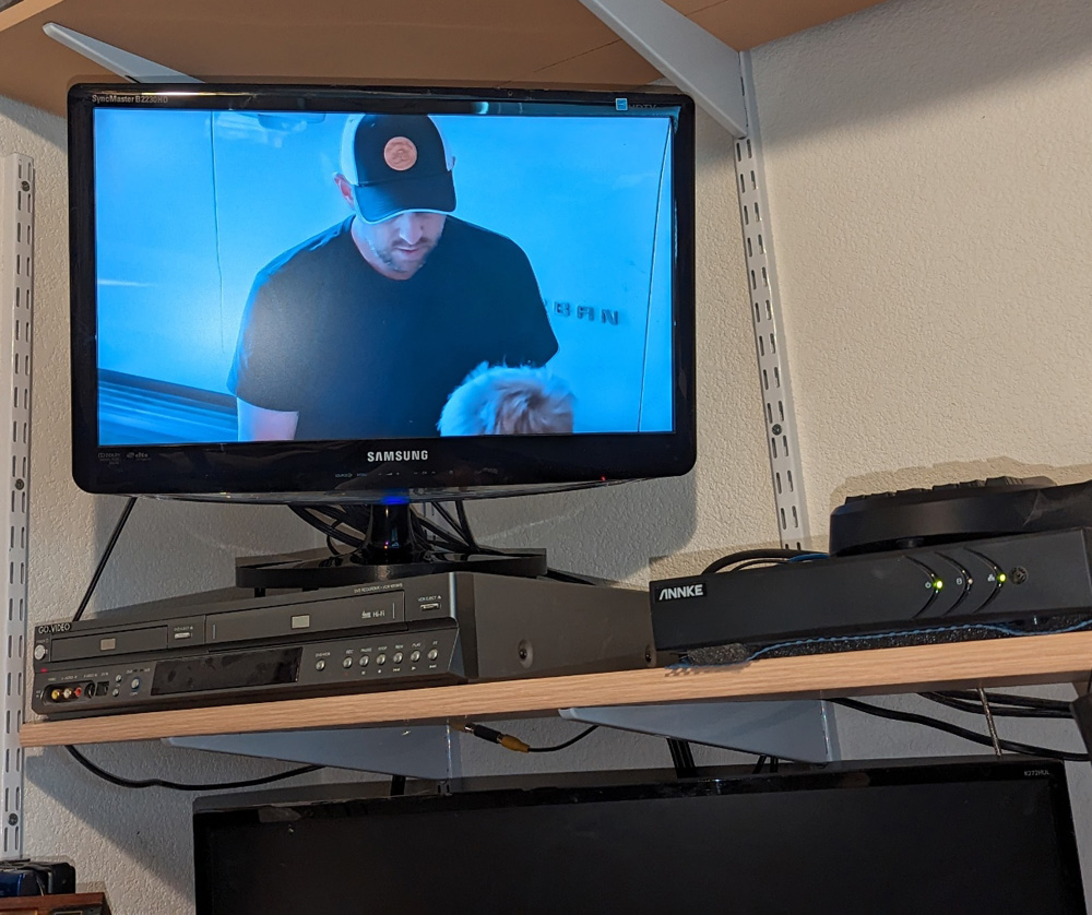
My office TV is placed on a DVD/VCR on a shelf, and is a couple feet above my head. To view it well, it needs to be tilted forward so I can view it head-on, otherwise the picture is washed out. For far too long, I accomplished this by placing an old battery pack (the first thing I found that was the right thickness) under the rear edge of the TV base. This tilted it at a good viewing angle, but was much too close to the tipping point of the whole TV. I finally decided that it was time to make a proper adapter which would still tip the TV forward, but do it in a manner that was stable and safe!


I initially picked the first thing I found that was the right thickness, a dead RC car battery, to put under the rear of the oval TV base to tilt it forward.
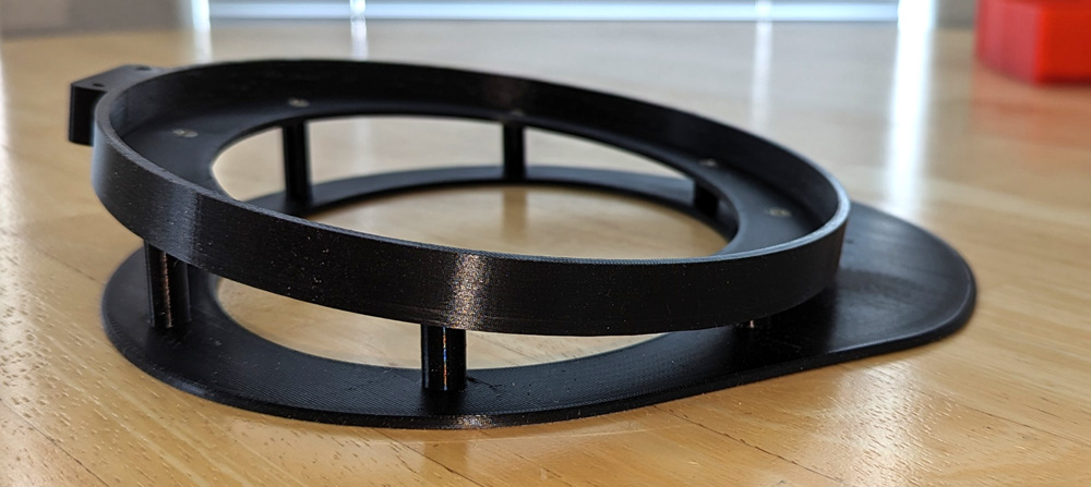
The tilting adapter I made is an oval ring to fit the TV base held at an angle to a base ring. The top has clip on the rear
to keep the TV from tipping out of the base, and the bottom ring is extended a couple inches on the front to assure stability
and keep the entire assembly from tipping forward.
My TV now still tilts forward, but is stable and secure!
Cloner Stand
I have a marvelous device called a Cloner Alliance View Pro which is a standalone video recorder which can accept almost any video source. I use it quite a lot. The built in display is wonderful, except it is at an awkward angle when place flat on a desk. I decided it needed to be at a slight angle to be really easy to use. I quickly designed and printed a framework which does just that.

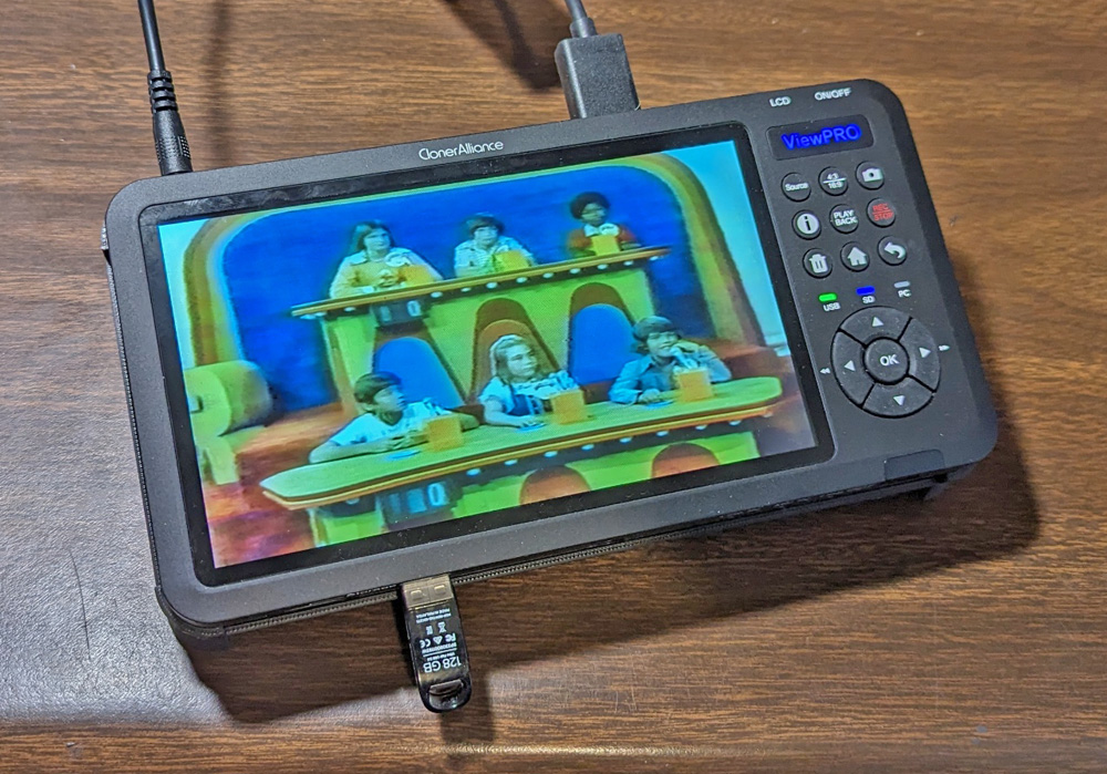
The left shows my View Pro and the frame I printed to support it at an angle. Note: The boy in the image is my son, who is now retired and has two married daughters!
Though hard to show in a picture, the right shows the device in its angle stand.
Heel Lifts
Whether due to nature, or a couple knee and an ankle replacement, my left leg is somewhat longer than my right one. My orthopedic doctor gave me a pressed cotton heel lift to put in my right shoe which helped, but only partially. He apologized for not having a thicker one. I thought of the idea of printing my own, but procrastinated until a neighbor - out of the blue - asked if I could print a couple of heel lifts for her. Her doctor had told her what she needed, so I told her I would try. I bought a spool of TPU, a somewhat flexible filament and printed her a pair. It took a couple of tries before they were just right for her, but she was very happy with them.
Then I decided it was time to print my own. I printed one and showed my doctor. He was impressed and made a couple small suggestions for improvements. I ended up printing two of them and put one in each of the pairs of shoes I mostly wear. They work great! I no longer lean to the right when I think I am straight!
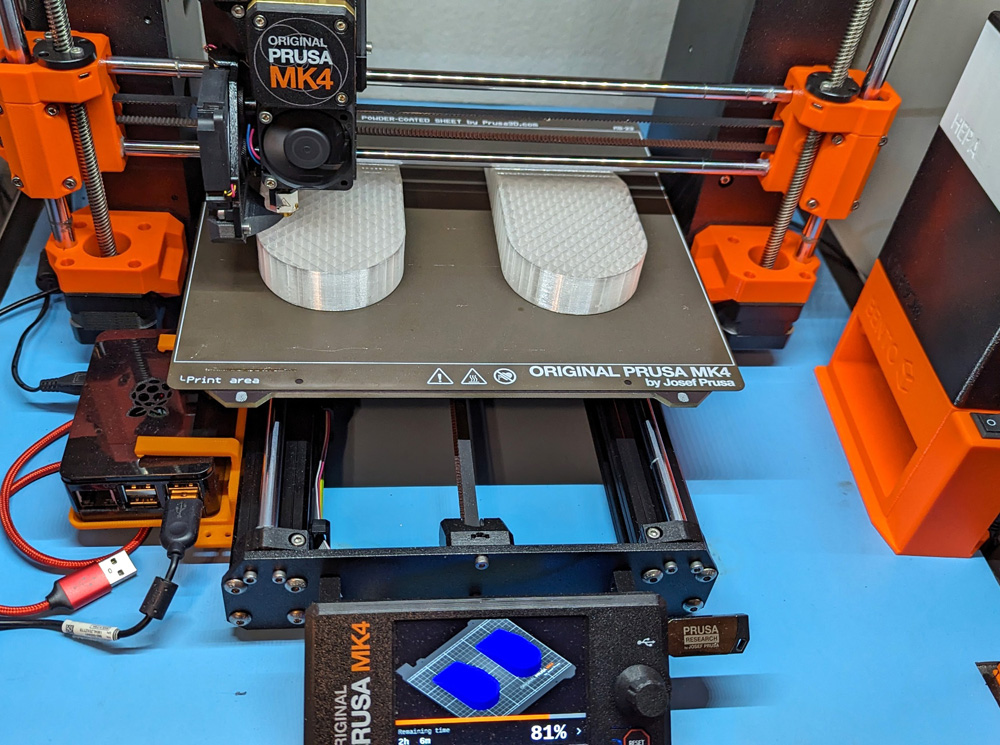
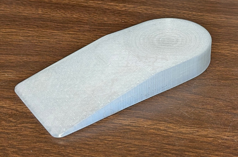
I am printing a pair of heel lifts for my friend on the left. On the right is the final version of my own heel lift.
Tissue Holders
For some time now, I have kept a box of Kleenex and a box of Kimwipes (tougher tissues bought at auction from my former employer when they moved the operation to the East Coast) on my side desk. These boxes have always been a nuisance and in the way. I decided to print box holders for the two sizes of boxes and mount them off the surface of my desk. I first had to figure out how to print the boxes without needing to have massive areas of support material. They came out fine and I am well pleased.
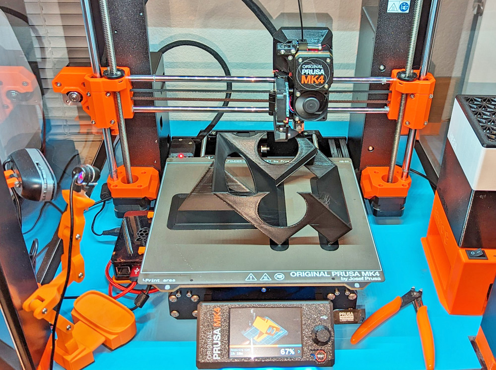
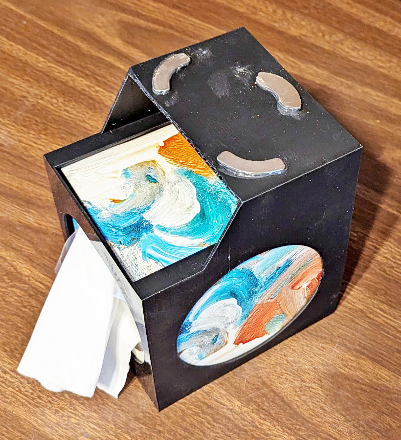
The boxes I designed could not be printed normally without having fairly massive areas of support material. Anywhere there is horizontal area of material in mid-air, supports
must be used or the molten filament will just fall. Angles of up to 45 or 50 degrees from vertical work fine, but much past that and again the material will either droop or fall.
By printing my cubes along an edge, all my angles are straight or 45 degrees and print just fine with the only support being a thin wall to steady the cube on its edge.
The right shows the finished Kleenex box. The raised area goes up to the bottom of the flat shelf to attach with magnets, while the front is low enough to clear the flange at
the shelf edge and the outlet strip I have there. I use a tapered construction shim to wedge the rear of the box in place to keep it from being pressed out during use. If
that had not worked so well, I would have added a clip on the rear to hold the box in.
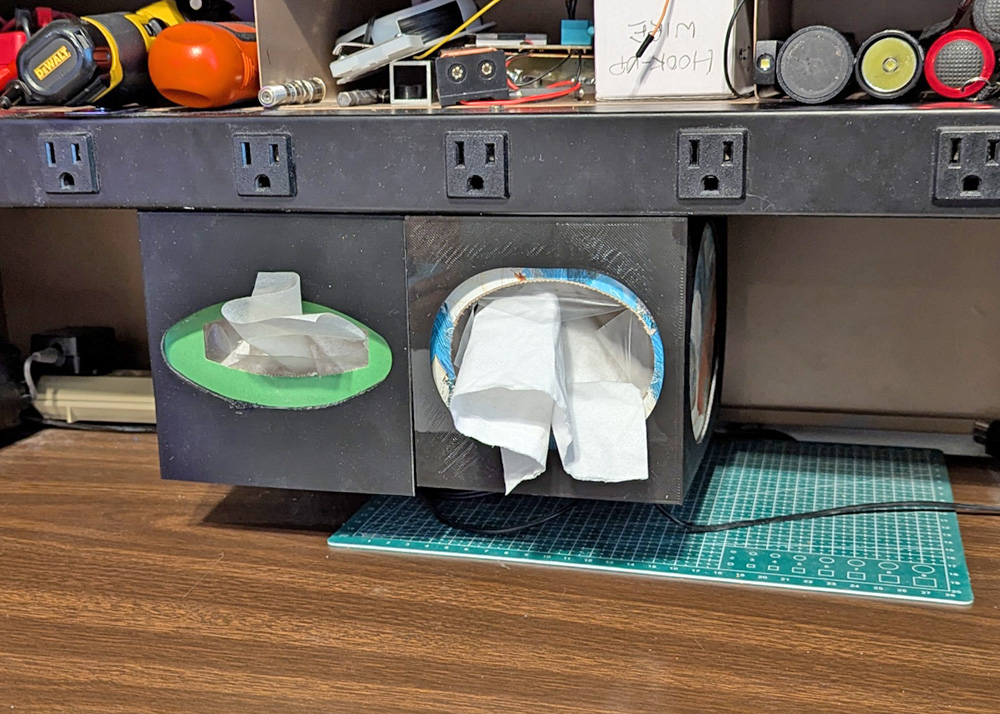
Mounted in place, the tissues can just be pulled when needed. The boxes leave a space below for cables and flat items. They
are attached to the shelf above using magnets, so are easy to remove to replace the contents, or relocate along the shelf.
Deej Mixer
I recently saw an article on the Internet describing a multi-channel audio mixer which plugs into your computer using a USB cable. It can be built with the desired number of channels and those can be assigned easily to any audio source. The project was named Deej, probably pronounced DJ (but none of the YouTube presenters did). Once I became aware of it, I found many videos and articles referencing it, all with rave reviews and description of its excellent operation. I decided to give it a try!

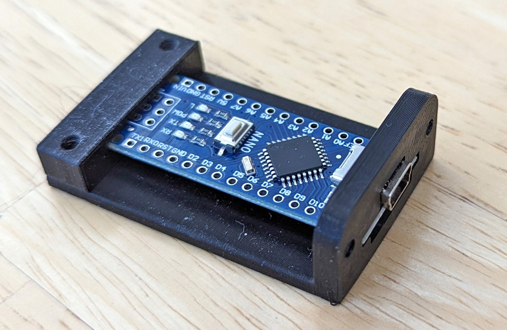
After a quick breadboard setup to prove it worked, I designed and printed the basic case and the mount for the Arduino Micro controller. I decided to make
a 5 channel mixer which gives me a spare channel or two.
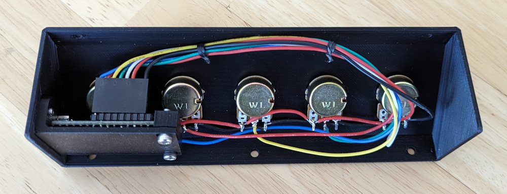

Wiring was quite simple and much less than you would think. These views show the functionally completed unit.

I ran several trial runs for the label, and ended up with this one. It had the best legibility and quality,
with only a couple small spots where the white text did not quit fill in. I had to use white paint
to touch up these dots.
The performance is outstanding! The Master is identical to the main volume control using the tiny speaker icon
on the task bar. The Chrome knob controls the volume of any sound coming from my browser, think YouTube!
The best control of all is the Zoom knob. Zoom meetings always have been significantly louder than other audio,
and required me to click on the speaker icon, click on the pointer and drag it down. Then I had to repeat the
process and drag it back up when the Zoom meeting was done. I had tried doing this using the Windows mixer,
but it went away when the Zoom call was over, and came back the next time, again set far too loud. The Zoom
knob stays right where I left it and there is no more fiddling each time. I have not yet activated the remaining 2 knobs.
Webcam Mount
During the Covid pandemic, our computer society changed our normal in-person meetings at the public library to remote Zoom meetings. As things started to return to normal, we decided to try some "hybrid" meetings, where we would have both in-person and remote Zoom attendees. This was technically challenging! In working out the details of how we would make all our proceedings equally accessible to both local and remote members, the need for a webcam showing the local members became apparent. Initially we mounted a webcam on a camera tripod, which worked well, but was a hassle to transport, set up, and take down.
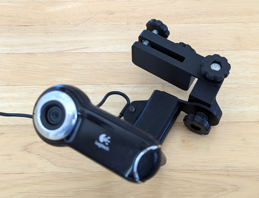
The library recently installed a beautiful, new A/V setup comprising a pair of large flatscreen TVs, webcams, and an integrated sound system. This solved most of our earlier problems. We attempted to use one of their webcams for our audience view, but limitations to the system made it unavailable to the computer which needed it. To avoid the tripod hassle, I designed a clamp-on, fully adjustable mount for the camera which allowed attaching it under one of the TVs.

The left shows the library mounting of their webcam under the flat screen TV. The mounting plate has a wonderful area for clamping my camera!
The right shows the mount I made. The top portion clamps to the aluminum angle, and the mount provides adjustments for leveling and rotating the camera. The camera itself provides
for raising and lowering. This bracket makes setup much faster than the tripod method, and will transport in my small parts bag.
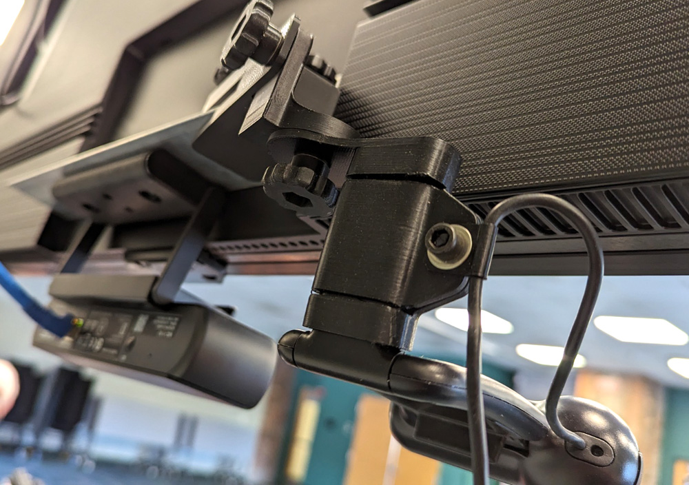
This shows the mounted camera from the rear. From the front, mostly all that shows is the camera.
Cable Holder
I have a spare monitor set up on the corner of my desk. I use this monitor occasionally as a 3rd monitor for my computer or for convenience when I am experimenting with some new electronics. When not in use the AC power and the HDMI cords are just laid on the desktop, where sometimes they slide down to the floor. It is always a hassle to find the cords when I want to use this monitor.
After fighting with it recently, I decided to do a quickie fix and solve the problem. Designing the part took about 5 minutes, printing took about 38 minutes and boiling some water and bending the tips up took maybe 10 minutes. From deciding to fix the problem to a finished, installed part took about an hour. My cords are now always off the floor and where I can immediately find them.

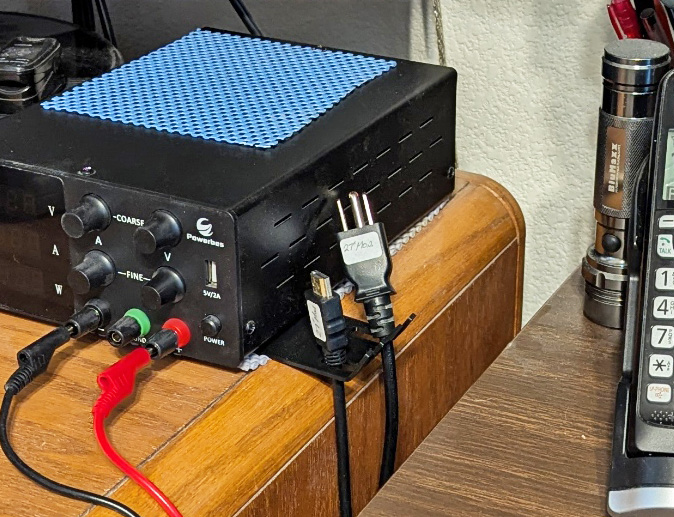
The cord holder was a very simple flat part, which I then heated to bend the ends up to restrain the cords. I hold it in place with the weight of the power supply I keep handy.
Water Heater Vent
I recently had a new water heater installed. In looking through the manual it specified that an enclosed heater such as mine requires a minimum of 100 square inches of ventilation to the outside area to assure adequate burner combustion air. The existing vent was a small metal plate with louvers in it. The total size of the louvered area was less than 30 sq. inches.
I found a screen at Home Depot that was 8 x 16 inches, but it simply had a flat metal edge. I designed and printed a frame to mount and protect it. By splitting it in two, it still just barely fit my printer, so I printed two halves and epoxied them together. I used small steel pins to reinforce the joint. To cover the not perfectly cut hole in the door, I printed two more pieces giving me an inside frame, protection of the cut edges, and mounting bosses for the outside screen's attachment.
The plumber also suggested changing the drain from under the house to onto the garage floor, so any leak would be immediately seen. I printed a small frame to surround this pipe also.
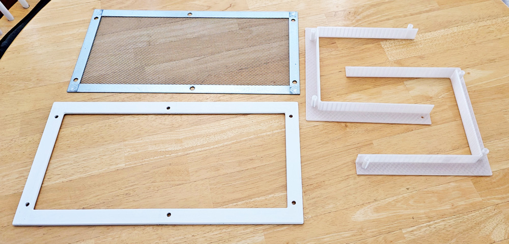
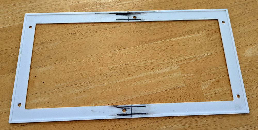
The pieces I printed along with the screen are on the left. I have already epoxied the halves together and painted it in this shot.
The right shows the rear of the frame and the joints reinforced with the small pins.

The finished installation allows much more air to the burner, and includes the added drain pipe.
Mini-screwdriver Case
I recently bought a precision mini-screwdriver with inertially controlled variable speed. It is the absolute top-of-the-line according to the reviews, and I love it - except -- it did not include a case! The best they did was the included cardboard box with a pair of nice foam inserts to hold the tool and its 24 included bits.
In looking through a couple 3D printing sites I found a case designed specifically for this screwdriver set. It looked quite good, so I printed it from his design files. It looks great and fits the parts perfectly. There was just one problem: The hinge setup was very wonky. The designer used links hinged to both the base and the lid. This means the the lid has no restraints when open and just flops and twists around. Of course it would work, but I want a "proper" hinge! If I had the true CAD file for this, redesigning the hinge would be easy, but as with most of these download-and-print items, only the printer file is provided, which is difficult to edit more than simple changes. I designed a part to replace his double-hinge-link, which fits the outline of the case exactly on the bottom end. The screw holds the shaped bottom tightly against the outside of the case, keeping it rigid. The top hole becomes the only hinge point, and is slotted slightly to allow proper alignment as you close it. I am now pleased as the lid is restrained when open.

The tool came with this box and the foam inserts. I had already moved the bits to the new case when
I took this picture, so there is only 1 bit in the foam, but it came full of bits.
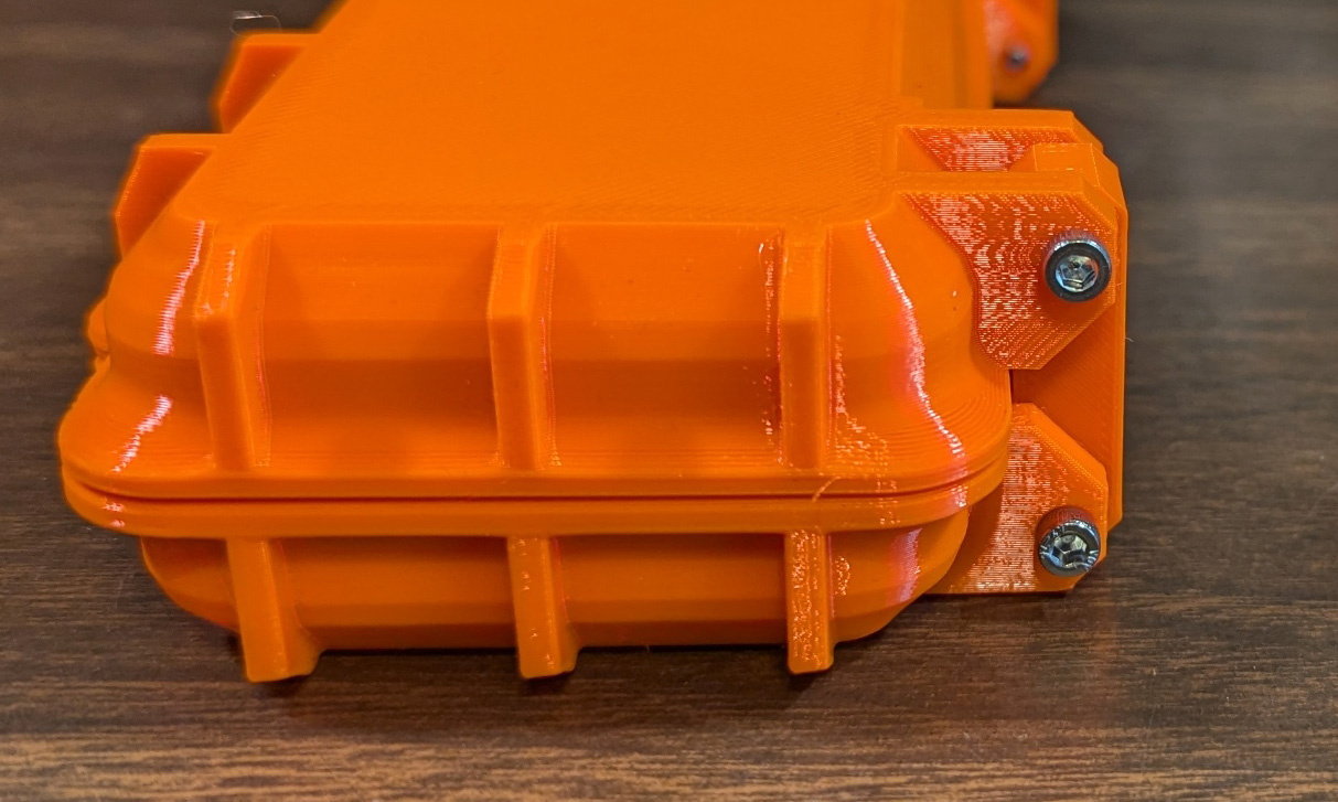

The end view of the case shows the two hinge points which originally used the black link on the right. The rigid link I designed is in orange on the right
and is shown installed in the left picture. Only the top screw is a hinge point now.

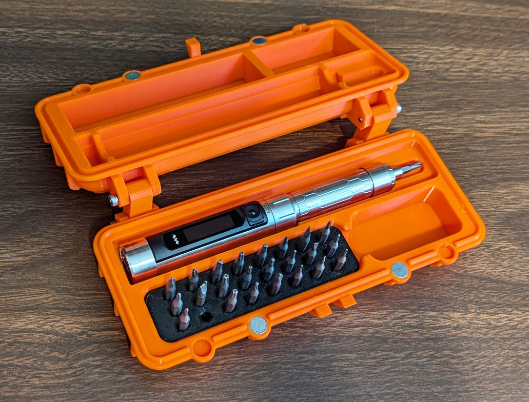
The case is an attractive, functional case which fits the screwdriver and its bits perfectly. There are magnets to hold it closed. With its modified
hinge system, I am totally happy with it!
Many thanks to zx82net who designed the Ultimate Parametric Rugged Box
and to 3DP-MAMSIH who adapted that to fit the ES15 screwdriver!
and to 3DP-MAMSIH who adapted that to fit the ES15 screwdriver!
CPAP Hanger
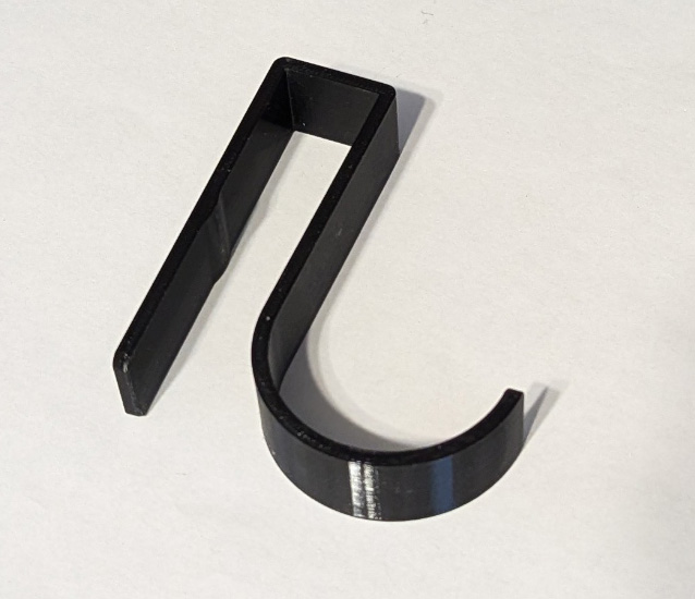
I need to use a CPAP machine at night. Along with its normal list of annoyances, during the day there really is no good place to put the hose and mask. I have been just stretching it across the head of the bed. A couple nights ago (as I write this) I decided to make a proper hanger for it. I rather quickly designed a simple hook that slips over a board on my headboard and provides a generous hook for hanging my hose and mask.
Component Tester Case
Several years ago, I bought a small universal component tester for about $7 after reading great reviews. When it did not arrive in a fairly long time, the vendor sent me a second one. About a month later the original one arrived! The vendor said to keep both. The original unit was described as coming with a Plexiglas case and a back light in the display. The replacement one was just a board with an attached battery holder, and the unit did not have a backlit display. I keep the "good" one in my shop and the bare board version in my office.
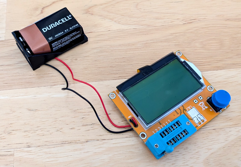
The replacement unit works fine, but is quite awkward with the
attached battery and no protection.
I decided to make a case for it. I measured the board and battery case accurately and drew 3D representations of them in my CAD program, then I drew the case parts around them. I was pleased that once I printed the top and bottom halves of the case they fit perfectly and I only discovered one small error, which was easily corrected, (See picture description below).

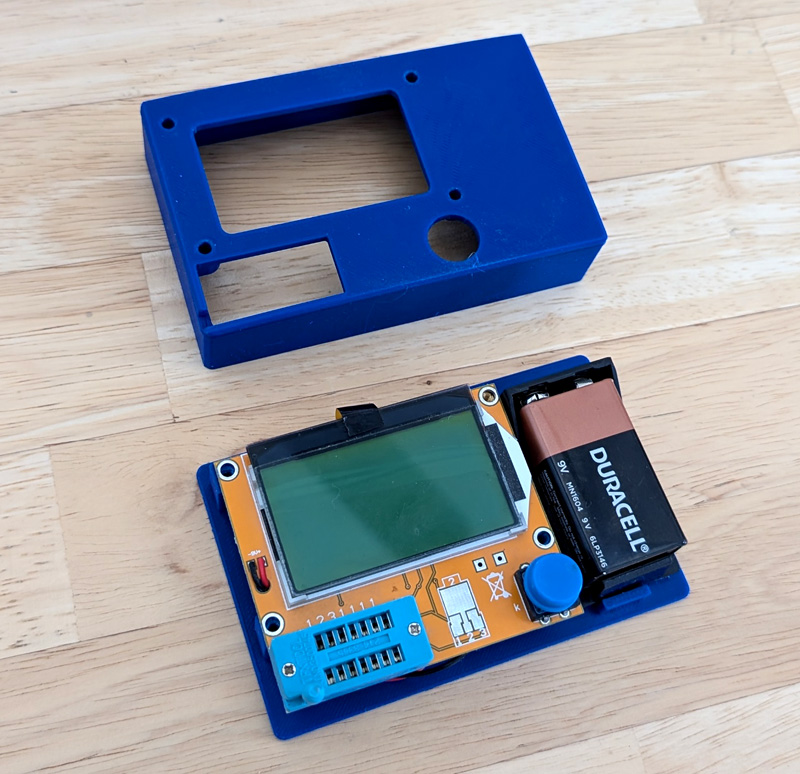
The two case halves sandwich the board and battery, and clamp the board securely between the mounting posts on both halves.
The one error I found was on one of the base mounting posts. As I used a single sketch to build both halves, the holes in the posts
were shown as two concentric circles, the larger one to clear the screws in the top, and the smaller ones to thread in the screws to
the bottom post. On one of the base posts, I accidentally selected the inner circle instead of the ring between them. The result was an
oversize hole with a post in the center. I drilled out the post, and sized the top end for a heat installed insert. Now I have brass threads
in that hole and the problem is solved.

And here is the finished case.
Cluttered Cord Manager
When I built my present main desktop computer, I moved my old one to my side desk for use as a secondary system. I have done this for several iterations in the past.
I wanted the flexibility of being able to easily change peripherals of this computer and being able to use the keyboard, mouse, and monitor with other systems for testing and repair. To this end I made sure all the cables coming up from the computer under the desk had a termination on the desk. This made it handy to connect most anything the way I wanted for the moment, but left a major clutter of cables. The terminations consisted of extension cables which ended on the surface of my desk. From there, all the peripherals plugged into those loose cables.
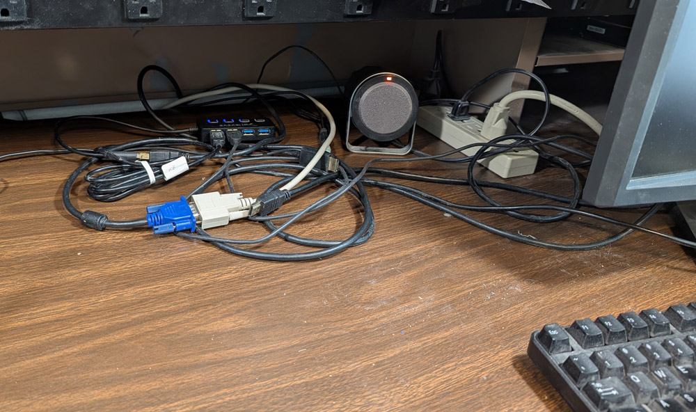
This is the clutter on my side desk, and this is highly sanitized, after removing 2 power cables and one USB cord that were never removed after
testing other devices, and were tangled into a non-decipherable mass! It was just a large pile of assorted, hard to identify cables.
I then started designing my tray with openings and clamping blocks for each connector along with a provision to attach a USB hub to the bottom. As done with several previous projects, I wanted to mount it to the steel shelf with magnets. Over the years I have scrapped many defunct hard drives, which all contain very powerful neodymium magnets and I have a pretty good collection of them by now.
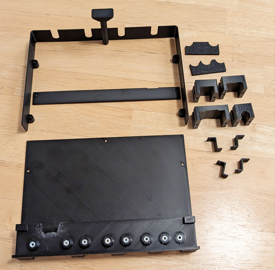
I ended up with more printed parts than I had expected, but here they are. The flat strip near the top mounts
on the two tabs of the main frame and provides support for the vertically mounted magnets. The
two scalloped pieces are spacers which mount the horizontal magnets at the correct height. The 4 blocks
are each tailored to closely fit the cables I need to mount and securely clamp them in place. The 4 "Z" clips
mount the USB hub.
This picture also shows the "cutout of shame". A groove to fit the VGA plug did not continue all across the top
mount piece, and with the narrow gap around it would have been very hard to correct, so I just cut that section
out. The easiest way was to use a hot-knife tip on my soldering iron. It made a real mess of melted plastic
around the cut which took far longer to clean up than the cut took. I really am not worried about the looks
as it is totally hidden by one of the magnet blocks, and that is totally hidden after installation.
This view also shows the pressed-in nuts used to screw in the cable clamping blocks and the 4 mounting
tabs for the USB hub (not shown). Hexagon shaped pockets are printed, then nuts are pressed in. This makes
for a secure metal to metal connection where screws are expected to be inserted and removed several times
during an items lifetime. Heat set inserts would also have worked well here, but all of mine are metric and
I am using 4-40 screws in this project.
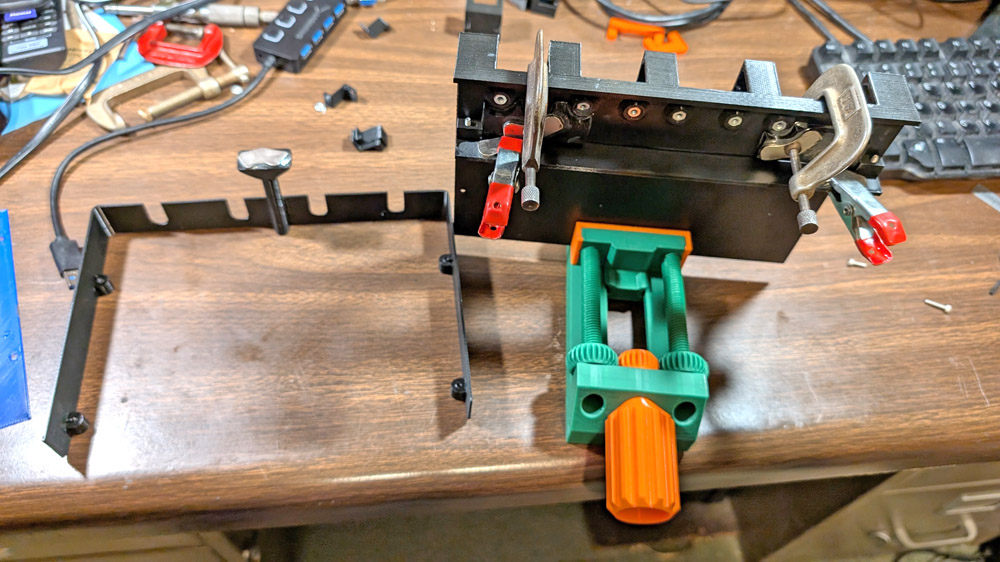
The messiest part of this project was epoxying the magnets in place. The main frame is being held
by a vise I 3D printed.


And here is the unit fully assembled except for the cables. The four magnets in the foreground attach to the electrical receptacle bar along the
front of the shelf, which is itself attached with magnets. The magnet on the post in the rear attaches to the bottom of the shelf and merely
stabilizes the rear of the unit.
On the right, the USB hub is secured using 4 small clips.
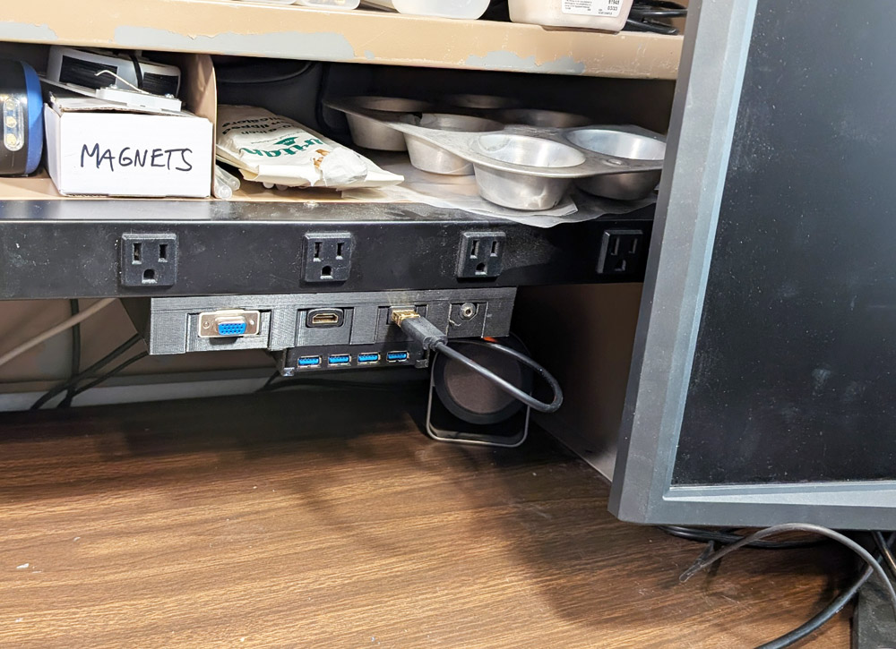
The system is now installed, and all the cables are readily accessible. I must have done my math correctly
as it is positioned just as I intended.
There was a power strip in this area also, adding to the clutter. I jacked up the end of the hutch (it is very
heavy) enough to slide the power cable under the hutch divider, into the right hand section. Here is is totally
out of the way, and practically invisible.

And here is my final setup, with everything connected and working. Now, not only is my desk much less cluttered, but also
it is easy to disconnect and re-configure everything as needed for testing peripherals or whole systems.
I recently upgraded my primary TV, replacing my previous set with a larger, top-of-the-line TCL system. My previous TV was also a TCL, but used a ROKU operating system. The new system uses a Google operating system, which is quite different, but I am getting along with it OK, with a couple of reservations which I will not cover here. One thing that did somewhat upset me was that I bought the flagship system from them, and the remote control still ran off a pair of AAA batteries. In other words, it was not rechargeable! In my opinion, for the price of this TV, it SHOULD come with a rechargeable remote!
I decided to do something about that!
|
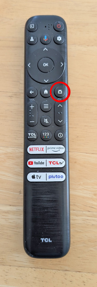
This is the remote which came with
my new TV. As you can see, it is quite tall and somewhat
ungainly. The existing batteries, and my proposed new circuitry
fit in the blank area under the bottom buttons.
I said I would not bring up my "reservations" about this remote - but I cannot help myself - so here goes: There are 2 complaints I have with the existing remote's function (not related to the batteries): First, there is no pause button on the remote. There are at least 3 different methods to pause the program, depending on the particular channel you are watching. Some require a double press of the OK button, some, a single press, and others require a press of the OK button, then an arrow down to a pause symbol, then a press on that. That's very annoying - especially when the phone rings and I fumble trying to figure how to pause my program! Second is the Live TV button (circled in red). I seem to press this often by mistake, mostly when pressing buttons by feel without looking. When this is pressed, it takes you to the built-in tuner, as it should, but the only way out is by pressing the HOME button, then re-selecting your previous channel. The BACK button does not back you out, as it does with every other function. Sorry, I felt the need to rant! |
 |
After doing some basic research, I decided that there really was not much involved in converting my present remote. By replacing the AAA batteries with a small lithium polymer (LIPO) battery, a small charge controller, and a couple of diodes, I should have what I want.
I did not want to wreck my existing remote, or not have the use of it during my conversion process, so as I was buying my other parts (from Amazon, of course), I looked at replacement remotes for my TV. First I looked to see if there were any that were already rechargeable, but naturally, there were not. I found that I could replace my existing remote from a number of listings for about $20, but there was a listing for "renewed, excellent" for $10. I bought that one. This was my unit to modify, with a minimum loss if the whole project were to fail. After receiving it, I looked on Youtube, but could not find instructions for opening my exact remote, so I started probing. Shortly I found where I could start prying the case apart into its two sections clip by clip, and succeeded in safely disassembling it.
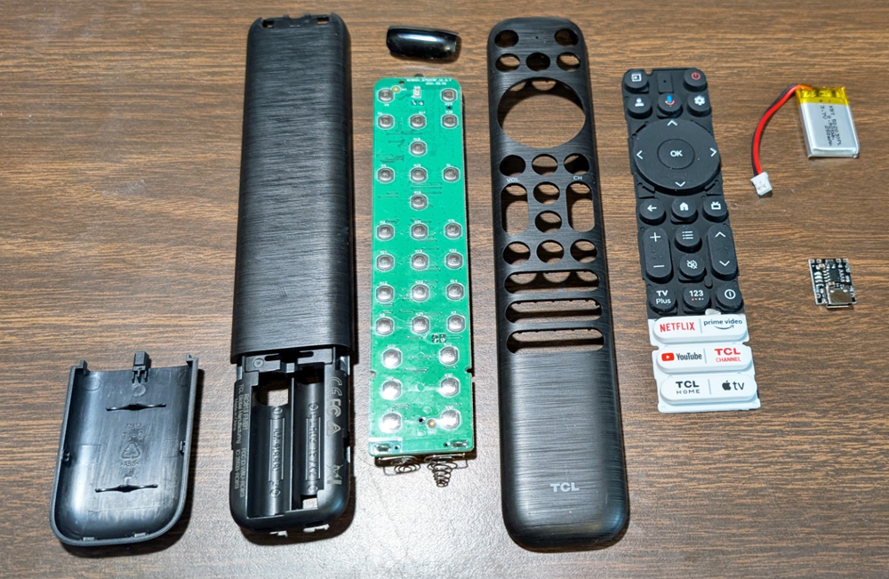
Here is the new remote after successfully separating it into its several sections. I also included
the new LIPO battery and a tiny charge controller.
While I had the remote in parts, I made a change that should minimize one annoyance I mentioned in my opening rant. On the bottom of the rubber buttons which transfer your press to actually click the snap type switch, there is a small cylinder shaped protrusion. By memory, I recall it being about 1/8 inch in diameter and maybe about .040 high. Using an Xacto knife, I trimmed this cylinder off, and even left a very shallow crater where it had been on the Live TV button. Now if I hit that button by accident, my normal light touch will do nothing. If I were to really want this function, a hard press will still activate that button. I don't expect to ever want to use this button, as I have a totally different system to watch live TV. Problem #2 solved!
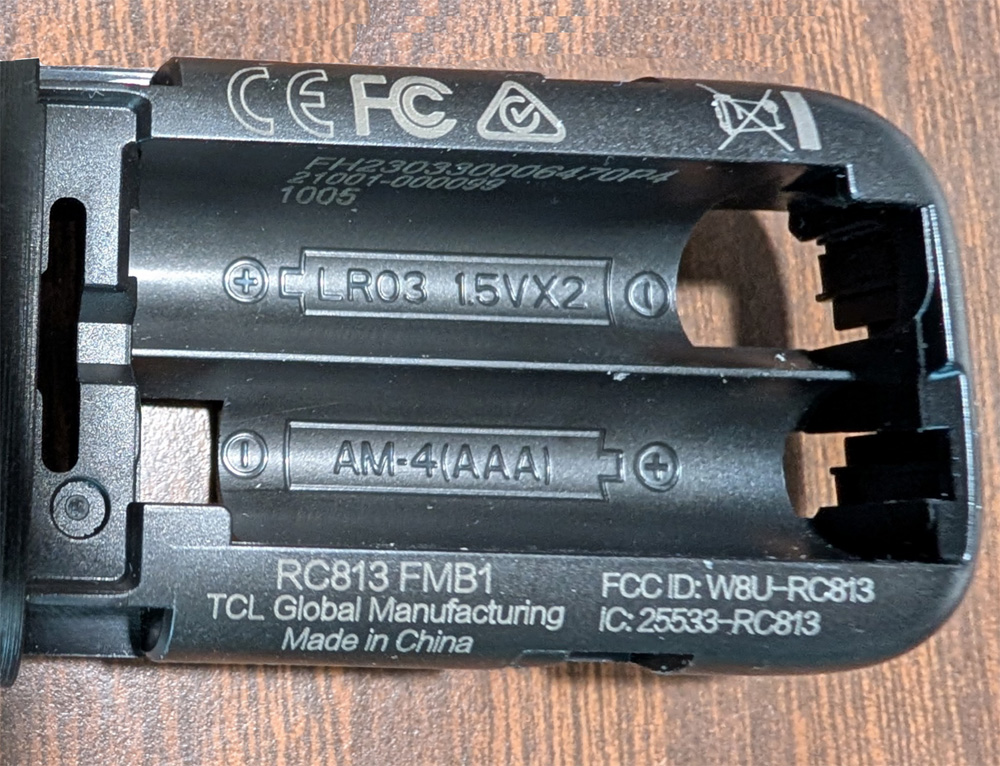
I had to mill away the divider between the original batteries to make enough room for the new parts.
I cut it down to the level which was deep enough for the battery with the controller on top. I then
allowed a little more for glue thicknesses. I also cleaned up the right end a little and cut a notch
for the USB C connector.
The wiring is really quite simple. The controller board has the USB C connector I will use for charging, plus 4 terminals needing to be connected . Two of these are connected to the battery and the other two connect to the remote, where the old batteries were connected. Originally I was going to cut off the tiny connector on the battery leads and solder the leads directly to the controller. Then I figured, especially on the first "prototype" unit, I would really like to be able to unplug the battery quickly if anything went wrong. I ordered mating connectors to the ones on the battery, which came with short leads already attached. I wired the battery through this connector, then to the controller. On the output end, I wanted to lower the voltage slightly, as the original batteries had a nominal voltage of 3.0 volts, and the LIPO has 3.7 volts. I ran one of the wires for the remote power through 2 diodes in series. The drop through these diodes resulted in a voltage of almost exactly 3.0 volts going to the remote.
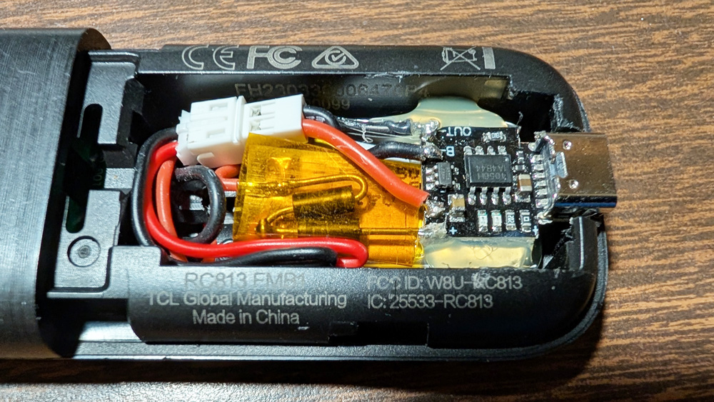
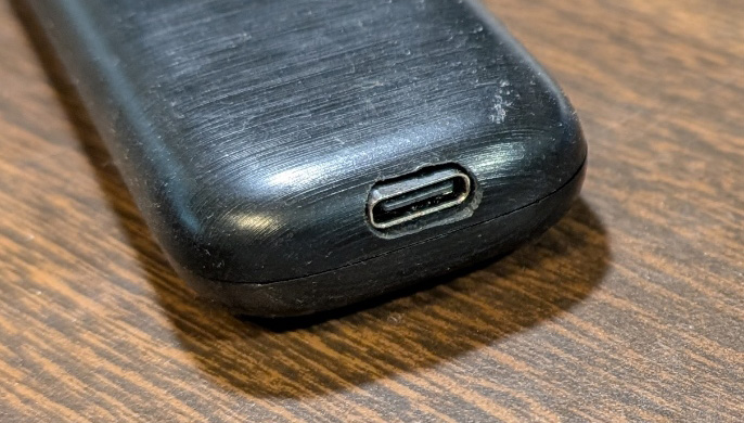
Here is the completed assembly. The LIPO battery is on the bottom with the controller board on top of it. The wires
managed to tuck into the remaining cracks without too much room to spare.
The only way the finished remote looks different from the original is the presence of a USB C connector on the bottom.
So far, everything seems to work
just fine. I have not actually tested the recharging, as the
battery is still at the fully charged voltage. I will have to
wait until I discharge the battery somewhat before I can verify proper
recharging.
Minor improvements to my CoreOne 3D printer: 12/2025
Something I noticed on my Prusa CoreOne printer is that when the table is up at printing height, it looks slightly tilted. The line of the table just did not line up with other horizontal lines in the printer.
The way the table is set to be horizontal during the Z axis calibration is that the table is driven slightly past the bottom of its travel, causing each of the leadscrew stepper motors to stall out as the table bottoms against screw heads at the bottom of the case. This is not at all harmful and is a common method of alignment. Now the table is close to being level and prior to each print, the table is sensed by the nozzle at a number of locations. This operation develops a correction table that compensates during printing for any overall mis-alignment or slight warps or bends of the table.
This system works very well and assures accurate and high quality prints even if there is fairly poor table alignment. However, I want the machine to be as accurate as possible before this correction takes place.
My first task was to take measurements to see if the table is parallel to the nozzle movement. A good way to do this is to mount a dial indicator on the extruder and sample spots around the table to see if the nozzle is always the same distance from the table. In the end, I decided to mount the indicator to a 3D printed box which I could put over and remove from the extruder motor. The box is a close fit to the motor and should return to very close to the same position each time I put it on.
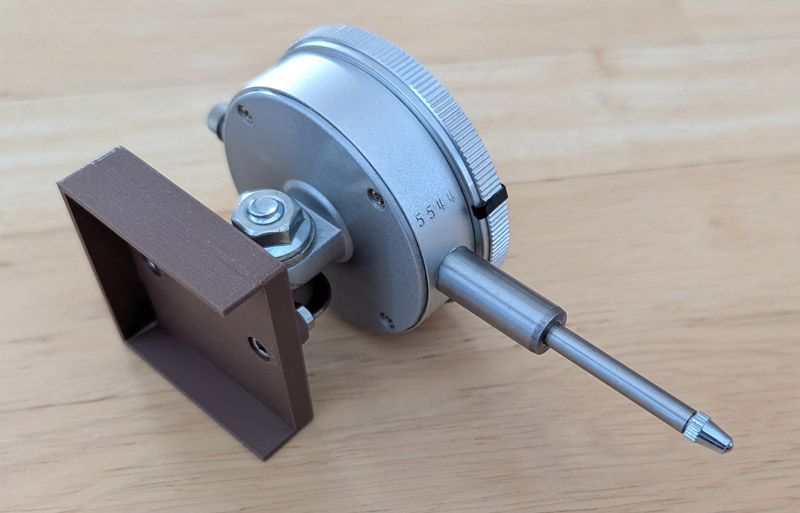
The box is a snug fit over the extruder motor and holds the dial indicator
in a very repeatable position
The results of these tests showed that the right and the rear leadscrews positioned the table height within 0.010 of each other, but the left side was 0.040 higher. To correct this, I designed small pads which would slip over the leadscrews and be positioned by snapping over the heads of the motor screws. I printed these pads to 3 different heights as determined by my indicator readings, installed them over the base of each leadscrew, and re-tested. The table was now within about 0.005 of being parallel to the nozzle movement. The automatic table leveling will now easily correct for this.
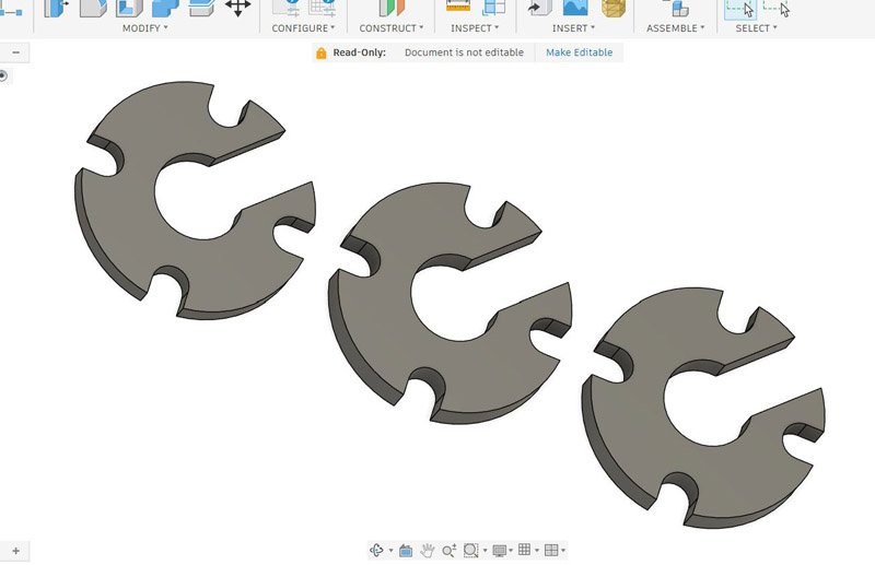
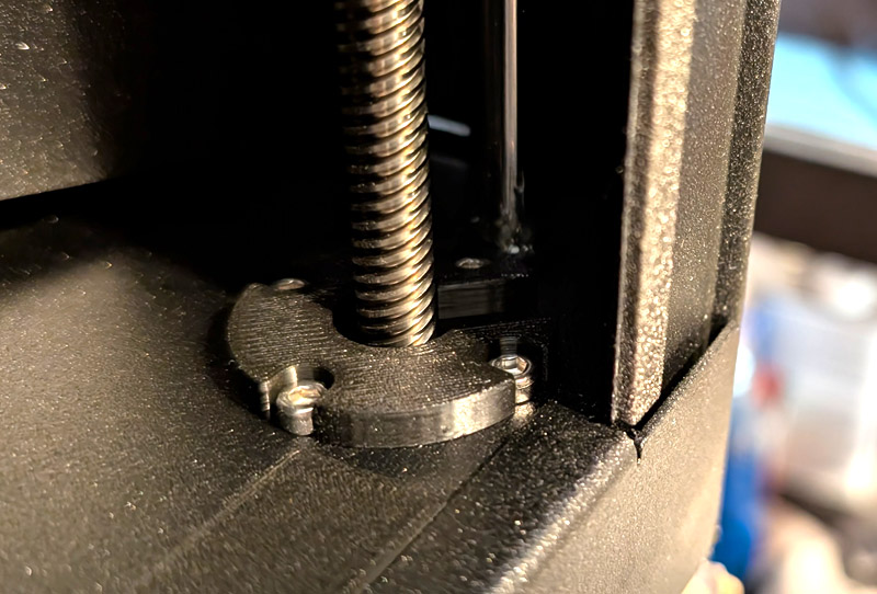
I repeated my basic design and then extruded the pieces to 3 different thicknesses as required. On the right is one of the pads installed.
I don't know if the printer is any more accurate now, but I feel better seeing a table that looks totally parallel to the printer body!
Another minor fix:
Periodically pieces of filament and other litter find their way into the bottom of the printer housing. It is easy to reach in and slide them forward, but at the very front, there is a metal flange over the floor. This makes for a smooth case outline with no edges showing, but it also makes a step-up at the very front of the case. It is very hard to remove tiny pieces of debris as they hit the flange and stop. Most pieces are too small to easily pick up, and sometimes I have to get a pair of tweezers to remove them.
My solution was easy; I printed a wedge (in 2 pieces) that ranges from just a few thousandths of an inch on one edge and the thickness of the offending metal on the other. I stuck these along the front against the metal flange. Now anything that I need to remove from the case just brushes up the ramp and out. Problem solved!
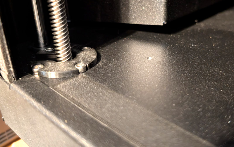
The printed ramp runs the full width of the opening. Here you can see it and the
left bump pad. The ramp makes it easy to just brush any debris out of the printer.
Minor improvements to my CoreOne 3D printer: 12/2025
Something I noticed on my Prusa CoreOne printer is that when the table is up at printing height, it looks slightly tilted. The line of the table just did not line up with other horizontal lines in the printer.
The way the table is set to be horizontal during the Z axis calibration is that the table is driven slightly past the bottom of its travel, causing each of the leadscrew stepper motors to stall out as the table bottoms against screw heads at the bottom of the case. This is not at all harmful and is a common method of alignment. Now the table is close to being level and prior to each print, the table is sensed by the nozzle at a number of locations. This operation develops a correction table that compensates during printing for any overall mis-alignment or slight warps or bends of the table.
This system works very well and assures accurate and high quality prints even if there is fairly poor table alignment. However, I want the machine to be as accurate as possible before this correction takes place.
My first task was to take measurements to see if the table is parallel to the nozzle movement. A good way to do this is to mount a dial indicator on the extruder and sample spots around the table to see if the nozzle is always the same distance from the table. In the end, I decided to mount the indicator to a 3D printed box which I could put over and remove from the extruder motor. The box is a close fit to the motor and should return to very close to the same position each time I put it on.

The box is a snug fit over the extruder motor and holds the dial indicator
in a very repeatable position
The results of these tests showed that the right and the rear leadscrews positioned the table height within 0.010 of each other, but the left side was 0.040 higher. To correct this, I designed small pads which would slip over the leadscrews and be positioned by snapping over the heads of the motor screws. I printed these pads to 3 different heights as determined by my indicator readings, installed them over the base of each leadscrew, and re-tested. The table was now within about 0.005 of being parallel to the nozzle movement. The automatic table leveling will now easily correct for this.


I repeated my basic design and then extruded the pieces to 3 different thicknesses as required. On the right is one of the pads installed.
I don't know if the printer is any more accurate now, but I feel better seeing a table that looks totally parallel to the printer body!
Another minor fix:
Periodically pieces of filament and other litter find their way into the bottom of the printer housing. It is easy to reach in and slide them forward, but at the very front, there is a metal flange over the floor. This makes for a smooth case outline with no edges showing, but it also makes a step-up at the very front of the case. It is very hard to remove tiny pieces of debris as they hit the flange and stop. Most pieces are too small to easily pick up, and sometimes I have to get a pair of tweezers to remove them.
My solution was easy; I printed a wedge (in 2 pieces) that ranges from just a few thousandths of an inch on one edge and the thickness of the offending metal on the other. I stuck these along the front against the metal flange. Now anything that I need to remove from the case just brushes up the ramp and out. Problem solved!

The printed ramp runs the full width of the opening. Here you can see it and the
left bump pad. The ramp makes it easy to just brush any debris out of the printer.
GO BACK
R. S. Mason 2024 - 2025
