

The package as we received it is on the left, wrapped in typical plastic as foreign packages often are. On the right are the contents of this package. The
received package consisted of the main printer box and 4 boxes of plastic filament I ordered at the same time. All the printer parts are very well organized
making it easy to pick the correct parts for each step.
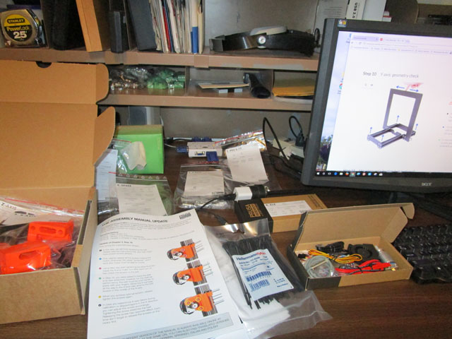
David sat at my side desk at my backup computer set to the on-line assembly manual, and picked the correct
parts for each step I was working on. This system worked extremely well. Construction went quickly and we
each learned a lot.
Their assembly manual is the best I have ever seen! Every step is described in detail with many very clear pictures. All the parts are separated by assembly step so it is easy to locate each of them. As they are referring to a part, they use color coded arrows and circles to make sure there is no confusion as to which part they mean. The computer version has a wonderful feature (in addition to always being updated to the latest details) and that is if you need to see the detail in a picture better, you click on it and it displays much larger. The printed manual doesn't seem to work that way!
By about noon, we got started actually building! This was a full 5 hours earlier than if we had just waited for delivery!
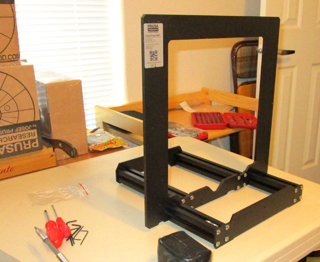
Assembly started by assembling the basic framework. This frame holds all the components of the printer
and must be very square and rigid.
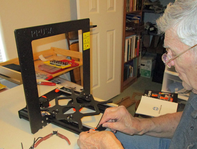
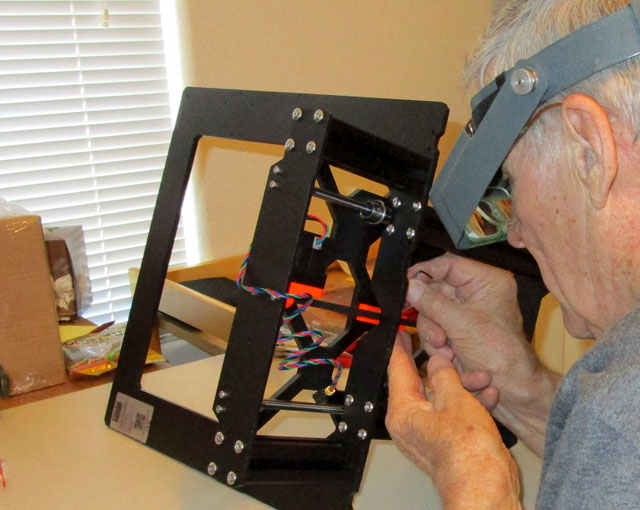
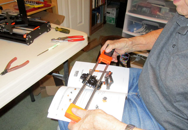
On the left I am assembling the linear ball bearings for the Y axis and the precision rods they ride on. They must also be aligned precisely. The manual details
how to do this easily. On the right I am installing and adjusting the lug belt which positions the table along the Y axis.
The X axis assembly is one of the simplest. A carriage rides on precision rods with linear ball bearings. A stepper
motor at one end drives a lug belt to position the carriage.
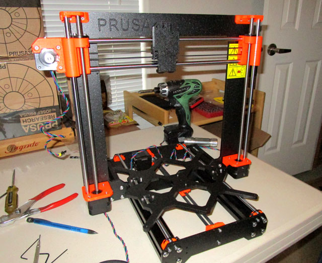
Next, this completed X assembly is mounted on a pair of vertical rods and two stepper motors and leadscrews forming the Z axis. All the positioning components are now
complete. The table moves the work in and out for the Y axis movement. The carriage moves left and right to position the extruder correctly in the X axis, and
that whole assembly moves up and down to the correct Z height.

Now the extruder assembly is built up and installed on the carriage. There are many, many wires coming from
this assembly. These include heater power, heat sensor, extruder stepper motor, filament sensor, sensor to
set exact height above the table, and power to the two fans. There is also a nylon rod which will be bundled
with the wires to maintain the shape of the bundle as it moves.
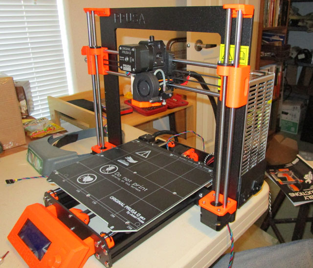
Here we see all the wires from the last photo are now gathered into a neat bundle and covered with spiral
wrap. Also the heated table has been installed. This plate, in addition to housing the heater contains 20 very
powerful, high temperature magnets which hold the treated steel build plate securely in place, yet making
it easy to remove.
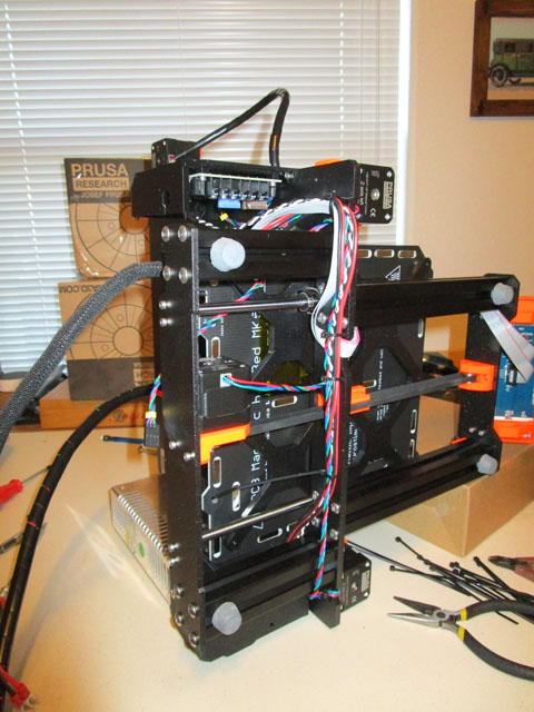

Prusa is very particular about wire management. They tell you exactly where to run each wire, where to place every zip tie, and often even which way
the zip tie is placed and where the head should wind up. On the right we see the wiring to the computerized controller, the Einsy board, named after Albert
Einstein because it is so smart. Pretty much every wire on the machine ends up attaching to this board.

We have finished the assembly of all parts of the machine. Now we have it fired up and are running the
automatic calibration routines. Among other things, these routines exactly measure any out-of-square conditions
and keep a correction table to make sure the parts come out exactly right.
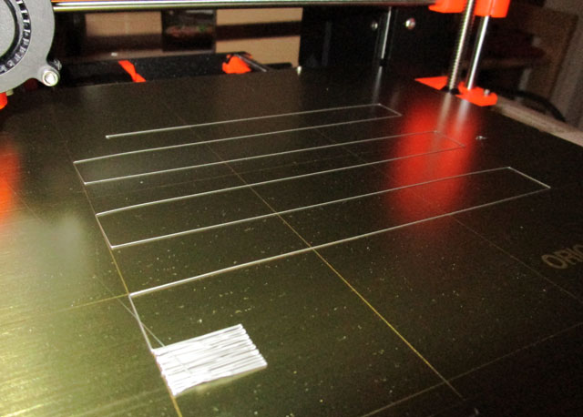
The first layer of plastic deposited is the most critical portion of the entire printing cycle. The height of the nozzle
over the table must be set very accurately, and cannot be done automatically. This is a test pattern to assist in
setting this height. As we see it here, we are still a long way from having it correct. When it is correct, you
can see that the zig zag lines are squashed to about half thickness, and the square at the bottom is smooth
and flat, with no voids or bumps.
After completing this step, we were ready to start making things!