|
|
||||||||||||||||||||||||||||||||||||||||||||||
| Summary
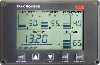
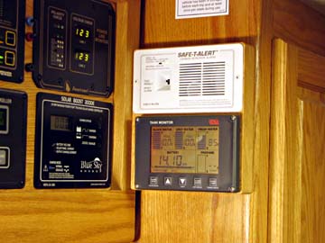
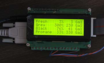
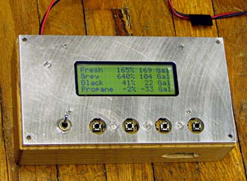
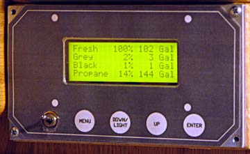
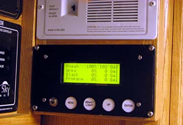
The Vena tank level monitor displays the level of the fresh water, gray water, black water, propane, and battery voltage simultaneously. It shows both a bar chart and a percentage full indication for each tank and the battery voltage. It reads in 5% increments, as sensed by capacitive sensors mounted on the outside of the tanks which send digital sidnals to the monitor head. Voltage reads in .05 volt increments. The propane uses the standard propane electric sensor that is part of the gage on the tank. With high expectations, I tried to do a first class installation and spent many hours doing so. Unfortunately, the final results did not justify the effort. In spite of the excellent resolution and the beautiful design of the monitor head, the resulting accuracy and stability in day to day operation were very poor. However, I have retained the description of the installation process. My ultimate solution was to design and build a monitor myself.
The description of that can be found following that of the Vena.
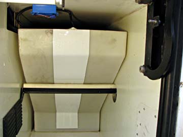
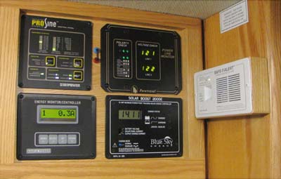
Planning The tank monitors in my Foretravel are much better than those in most RV's, but I still feel the Vena offers a number of advantages over the stock system. The Foretravel uses solid state pressure sensors at the bottom level of each tank, essentially weighing the height of the liquid above it. These sensors feed a computer which converts the pressure to "fuel gage" type displays with a resolution of 1/8 tank. The backup monitor displays these values with the change of a switch.. I have had minor reliability problems with this system, including having to replace one of the pressure sensors and then re-calibrating the entire system. The calibration routine is quite cumbersome, having to re-calibrate every tank for any change. Although the resolution is fairly good, the accuracy leaves much to be desired. The unique feature of the Vena system is that after you calibrate the tanks by filling each at a constant rate, the gage will read the percentage based on gallons, not just the height of the liquid. If your tanks are irregularly shaped, as mine are, this is a big advantage. Also, if a tank should require re-calibration for any reason, you can calibrate just that tank, not all three! I like the idea that the level display is constantly available, and that I don't have to turn on the back-up monitor to read it! My engineering instincts that tell me I have to know exactly what each system in my motorhome is doing, and I am much happier with a resolution (and presumed accuracy) of 5% of the gallons as opposed to 12.5% of the liquid height. In most motorhomes the resolution is 25% or 33%! There is also a provision to control your water pump from this panel if you desire. A control relay comes as part of the package. Installing this monitor requires placing 6 inch wide flat self-adhesive sensors the full height of each tank. Ideally this should be on the drain end, as the bottom of the tanks slope down to that end, and that would allow the gage to read all the way to empty. I have several problems mounting the sensors on my tanks. My tanks are as tall as the compartment height allows (about 26 inches) They run across the width of the coach, leaving space at each end for plumbing, etc. My tanks have a vertical face on the passenger side, but that is the high end of the tank. On the driver side, the tanks have a vertical face about 6 inches high, then the wall angles out at about a 45 degree angle for about 24 inches, then about 6 inches of vertical face. The tanks fill the width of the compartments, so mounting sensors on the side is not practical. Each of my tanks provides a unique problem for mounting the sensors.
The fresh water tank's vertical wall is totally inaccessible without removing the hot water heater, or the tank itself. I was not willing to do that! The angled end is accessible, but there is a steel channel mid way up the angled wall to provide support. I decided to mount the sensor on this end of the fresh water tank and modify the steel support to provide at least 1 inch clearance. This was the figure suggested by the Vena factory tech. Routing the sensor along this irregular end will use the entire 36 inches of the longest optional sensors they provide. The black water tank is long and high, but only 8 1/2 inches wide. The driver side (the low side) has the dump fitting coming out of the tank, leaving less than 4 1/2 inches of width to hold a 6 inch wide sensor. Of course this end also has the same problem of the steel channel. The grey water tank would easily accomodate the 6 inch sensor, but still
has the problem of the steel channel.
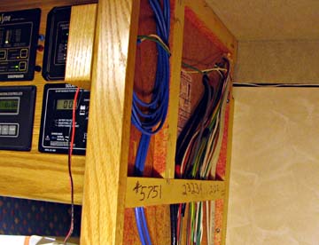
I decided to mount both the black and the grey water sensors on the high end of the tank. After slightly moving some plumbing at that end of the tanks, I had plenty of space for the sensors, even on the 8 1/2 in wide black water tank. I decided that the roughly 2 1/2 gallons of black water and the 5 gallons of grey water that it would take to reach the start of the sensor would not be a problem. This is about 5% of each tank's capacity, and I am much less concerned about the first 5% than I am about the last 5%!. Installation I started by running cat-5 network cable from the three locations I am monitoring to the location of the display module. This will be located in the area where other electrical monitoring equipment is located over the dinnette table. This is over the tank compartment on the passenger side, making the wire run straight forward. Each cable has 4 twisted pairs of conductors, and each will have spare wires. The fresh water cable runs over the tanks across the width of the motorhome
and drops down where the sensor will be located on the driver side.
The black and grey water wire drops straight down just a short distance
on the passenger side. The propane wire runs forward through the
main storage bay to the propane tank in the next compartment. All
these cables run up through a hole in the top of the compartment which
is the floor of the motorhome. The wires come up into the bottom
of the pantry, behind the ice maker. They then procede up in the
left hand hollow wall of the pantry. The instrument is mounted on
the outside of this surface. All the cables in the compartment bays
are in split wire loom.
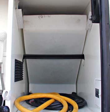
Mounting the sensors was the next task. I started with the fresh water tank. I had removed the steel support channel and modified it by mounting two lengths of heavy wall 3/4 inch PVC pipe on the surface. The diameter of this pipe is about 1 1/16 inch, giving me the 1 inch clearance the Vena technician indicated I would need for any fixed metal object. At this distance, there is still an influence on the sensors, but as long as it does not move, the calibration procedure compensates for it. As this end of the water tank is exposed, forming the back wall for
an area where I carry my electric cable, water hose, and two bins of utility
related items, the face of the tank had gotten fairly dirty. I first
scrubbed it a couple of times with a household cleaner. I then finished
with two thorough scrubbings using rubbing alcohol. I had a fair
amount of trouble installing this sensor, as I was working a ways back
in a 19 inch wide compartment, and the surface of the tank was not very
flat. It had slight bows and bulges making it very hard to keep a
flat sensor from wrinkling as it was squeeged in place. I managed
to keep the foil areas quite flat, but got some wrinkles in the plastic
area between. Getting a tight bond around the inside bend at the
lower end of the tank was also a challenge. In all, I am quite satisfied
with the result
After checking with the Vena techs again, I decided to mount all three sensors with the wires at the top end instead of the bottom as the manual suggests. This helped me with my wire routing, and on the fresh water tank helps protect the electronics board which is located where the wires come out. The two cautions the tech raised were that the board is much more succeptible to water damage as the wires leave an open pocket between the sensor and the tank where they exit, and that if the wires are allowed to flop over the sensor they will cause accuracy problems. Although all my sensors are in normally dry areas, I sealed the open pocket around the wires with silicone sealant, and the wires are all routed well away from the sensors. The black and grey tank sensors were much easier and went on without a problem. These tanks are within easy reach, were quite flat, and did not require as long a sensor. They were about 26 inches high. Again, I sealed the wire exits with silicone sealant. I decided to use wire loom over all the wiring in the bays, and decided
to use small electrical boxes to make my connections. I had to extend
the wires coming out of the sensors to reach the locations of these boxes,
but that was not a problem. I soldered and shrink sleeved the joints,
and they fit in the wire loom easily.
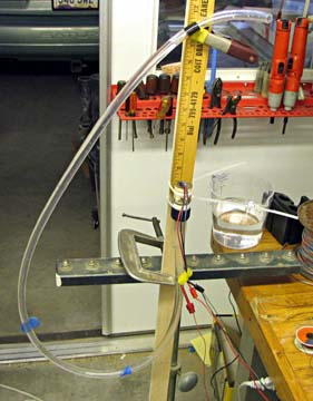
I chose to not connect the water pump or the alarm inhibiting ignition wire at this time, but have plenty of spare wires in each cable if I change my mind in the future. I next wired the monitor panel. I attached short power leads from a 12 volt supply that feeds the CO detector immediately above where I am mounting the tank monitor. I wrapped all the unused wires around the ends of the cables. Then I connected the active wires to the proper holes in the connector provided with the monitor, and mounted the monitor. When I connected the power, the panel displayed the voltage and showed 100% for each tank, except for the propane, which I have not connected at the tank yet. It displays "NO SIGNAL", a nice touch. I did the initial calibration by pressing the proper buttons per the manual, then filling each tank totally full at a constant rate. Each tank's calibration was successful as indicated by 3 beeps at the end. The water tank was easy, as I can see the level through the tank. To solve the problem of knowing the level in the black and grey tanks, I made a sight tube from a length of vinyl plastic and attached it to the hose drain on a sewer cap. I used a splitter here and also fed in the water to fill the tank. I used a rotating laser level (I just had to use a high tech solution to a simple problem) to set the mark on the plastic tube just at the top of the tank. The problem with feeding the water through the splitter was that I had to turn off the water to get an accurate reading of the water height. I did this for about 3 seconds about every minute. I figured this would have a minimum effect on the calibration. The sight tube would have worked much better if I had run a hose into the motothome and filled the tanks through the toilet or the shower. This whole process would have been much easier with a second person. After doing the linearity calibration runs, I lowered the level in each tank to where I wanted them to read 100% and calibrated the full points. Since I placed the sensors on the "wrong" end of the black and grey tanks, I had to put a significant amount of water in the tanks before it reached the sensors. This caused a problem for me on the grey tank, as there was no change of reading when the water level reached the sensors. In fact it still read 0% after I had put about 4 inches of water in the tank, as estimated by tapping on the tank. I ended up pouring a measured 8 gallons of water into the kitchen sink, then setting the 0 point, and all worked fine. I probably did not need quite the 8 gallons, as I wasn't allowing enough time for the gage to update. The manual says to wait until there is no change in 3 minutes. The black tank worked without a problem.
The technical problems I had to overcome due to my tank configurations and the items around them probably made this one of the more difficult installations, but I am very well satisfied with the results. I am about to head out for almost a week of dry camping followed by several more days of electric only. I am really excited about being able to know exactly where I stand with my tank capacities. Results: (Major Dissappointment) My first trip using the Vena Monitor was a disaster (tank level monitor wise). I started with the water tank full and the black and grey tanks empty. Early in the trip, the water tank read 70%, then over a matter of hours went back up to 100% The grey tank seemed somewhat more stable, but still had variations up to about 30%. The black tank was horrible! It jumped all over the scale! It would read empty, then a little while later it would show 30%, then it would show 80%, then back to 30. It had absolutely no coorelation to the actual level. Vena has been quite responsive (once they took me out of their "spam" filter). They correctly diagnosed that I had too little swing from empty to full, as read by a semi-undocumented "debug" feature. They sent me a new sensor for the black tank which truly seems to have a little more swing between extremes. I have calibrated that tank and will not know how well it performs until my next trip, but there has already been excessive variation in the readings, just sitting in my garage with an empty black water tank. I calibrated the zero level then watched the tank reading vary from 0 to 45% over a period of about two weeks. I spent a fair amount of time trying to figure out how I can connect
the Foretravel pressure sensors to the Vena monitor, and came quite close,
but apparently because they multiplex their power to the sensor and the
resulting signal back on the same two wires, it would work great on the
breadboard, and then blow up on the real unit. I eventually gave
up trying to modify something about which I had no information on the workings.
I have just written off the whole Vena experience! One high point of this experience is that it has spurred me into an area I have wanted to explore, but have kept putting off. Birth of the BasicX LCDX / Mason Tank Monitor aka. Mason's Marvelous Muck Monitor aka. SuperMon I enjoy fiddling with electronics and I enjoy fiddling with computers
and software. For a long time now, I have wanted to experiment with
a line of hobby microprocessor modules that are finding a huge acceptance
with the robotics crowd. I decided building a GOOD tank monitor would
be the ideal project to start with. The system I decided to go with
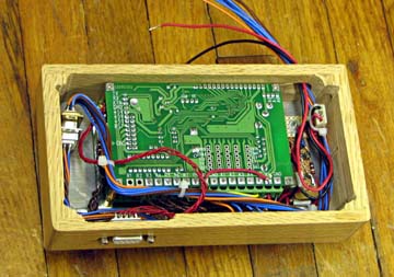
is a unit called BasicX, and the specific model I chose is the LCDX module.
This is a 4 line by 20 character LCD display which is already interfaced
to a BasicX microprocessor system. The module has a number of general
purpose input/output pins, 8 ten bit analog inputs (good to about 1/10
of a percent resolution), 8 relay driver outputs, 400 bytes of RAM, and
32k bytes of electrically erasable programmable read only memory (EEPROM).
The microprocessor is programmed using a fairly decent dialect of Structured
Basic, and this whole package cost $80, including the open source software
development system. For a few dollars more, I bought the development
kit. This included a power supply, a keypad, several cables, and
the software on a CD.
The tank monitoring system that Foretravel uses has the potential
to be a supurb system, but the implementation by their sub-contractor left
a lot to be desired. They use solid state pressure sensors connected
to each tank near the bottom. The pressure measured is directly proportional
to the height of liquid. The sensor device has an accuracy and linearity
of a small fractrion of a percent. Essentially they are operated
by connecting a voltage across 2 of the leads, in this case it is 7 volts,
and a third lead outputs a voltage that varies from 0 to 7 volts depending
on the pressure.. In our installation, the height of the tanks limits
the output to about 3 1/2 or 4 1/2 volts depending on the tank.
I will use the existing resistance sensor on the propane tank by supplying
a voltage through a series resistor, and reading voltage out.
I dug back almost 50 years and actually came out with enough Algebra to
solve the equation for the ohms of the gauge, given the non-linear output
voltage.
The LCDX module is perfect for developing my own tank monitor. It has twice as many analog inputs as I have tanks to read, the relay drivers should do nicely for turning the power on and off to the sensors as required, the display is quite adequate for displaying the tank information and any optional data I desire, it has a keypad input, and the RAM and EEPROM should be quite adequate for a project of this size. The only external circuit I should need is a voltage regulator. The LCDX power input is spec'd at 7.2 to 12 volts . As the house system runs at up to 14+ volts I will provide a 7.2 volt input power. This can then also power the sensors at near their original voltage. When my BasicX hardware arrived, it took me about a day, part time, to figure out how to get everything hooked up and how the editor and compiler worked. It took another day or two to get somewhat comfortable with the BasicX programming language. I printed out hundreds of pages of language definitions, command structures, and hardware descriptions, and of course I wrote the obligitory "Hello World" program. Finally I was able to start writing some meaningfull code. Gradually I got the Menu system to do what I wanted and started writing modules to do things like turn the backlight on and off, vary the brightness and contrast, write a variety of calibration values, and generate the calibration tables a couple of different ways. It will display almost anything you might want such as the contents of the calibration tables and the empty and full calibration figures, and the raw sensor outputs both in a count from 0 to 1023 and in volts. I can change the update frequency in a number of steps from continuous to once every 60 seconds, and I can send the table contents and calibration constants to an external computer. In addition to the above options, I also made it tell me the tank levels. My output is in 1 percent increments and whole gallons currently in each tank. Using the calibration system, I am reading the percentage of the actual gallons, not the height of liquid in the tank. Our tanks are small at the bottom, then taper out and are large at the top. Certainly not linear with the height of the liquid! After about two weeks of part time puttering, I had a pretty well checked out system. Everything seemed to work as designed, and I was putting out valid data with a simulated input. About this time I started trying out the relay drivers as a way to turn the power on and off to the sensors, and found more voltage drop across the driver switch than I had counted on. This made me overflow one of my tables, and as I discovered early on that I can only use 480 bytes of the EEPROM for variable storage, I had to try juggling table size, table increments, starting and ending points of the tables, etc. I ended up doing a major restructuring of the code that gave me fewer table entries, but larger capacity and much smaller code for the exact same functionality. Actually, I should have written it this way originally, but it's been a great many years since I have done any significant programming, and then I only puttered around at it. (That's my excuse.) By keeping my calibration tables and constants in the EEPROM, they never go away when I power off, yet my program can deal with them just like any other variable. The programming function is all automatic and invisible. I ended up with about 1150 lines of code in my program. The earlier version before the re-write was over 1800 lines. I examined the wiring I had done for the Vena system and discovered
I had enough spare wires running from the compartments up through the floor
to the cabinets above to connect these sensors and still leave the Vena
connected.
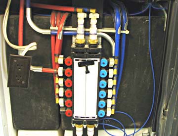
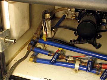
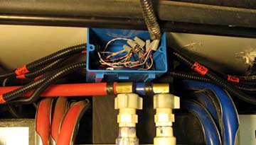
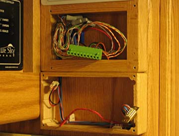
I replaced the shallow connection box above the water manifold with
a much deeper one. I left all the Vena wiring in place for now and
added new wire runs to each of the Foretravel pressure sensors. I
then ran all 8 of the resulting split loom encased bundles of wires into
this box and did all the various cross connections. All my sensor
connections, except for the propane now connect in this box, both for the
Vena and for the LCDX.
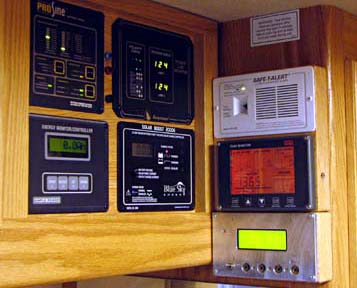
I temporarily fastened the single oak mounting frame I used for the
CO detector several projects ago below the current double one that now
holds the CO detector and the Vena. This frame holds the new LCDX
module below the Vena, and the wires run down through the bottom of the
double frame. I will need to replace this double frame with a slightly
deeper one for my final installation, assuming the Vena will be going bye
bye.
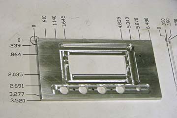
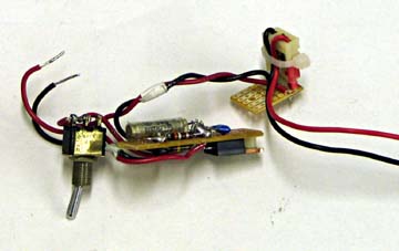
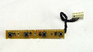
During the same time frame, I was designing and making the front panel
for the display, the push button assembly, and the voltage regulator assembly.
None of these is particularly difficult or time consuming, but there seemed
like a never ending stream of these small projects needed. I spent
a lot of time doing wiring harnesses also.
I spent the better part of a day getting all the assemblies wired and
installed on the mounting plate. I then fitted everything into the
oak frame to check for wiring clearance. It all fit, but was very
tight. I machined an extra 3/8 from each side of the frame and things
fit much better. Once I got all the wiring connected in the lower
connection box and in the Vena frame, I buzzed out all my connections.
The chance of error was high, as I had a many column table that connected
this color to that pin to that different color, etc. It turned out
that every wire buzzed out OK!
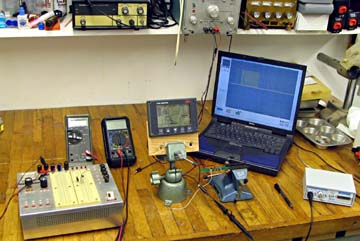
After completing the wiring and checkout, I re-installed the Vena and
installed the LCDX module. Everything powered up OK, but monitoring
the sensor voltages directly (using one of my menu options) I noticed a
fair amount of noise in the readings. They flickerd by over 1% on
the reading. I removed the Vena and un-plugged it. My readings
now only changed one or two counts (about one tenth of a percent per count).
As the Vena does not have a power switch (I have no idea why not!) I installed
one in the end of the Vena oak frame. I'm certain that running the
signals from the two systems through the same cables does nothing to help
the cross-talk. NOTE FROM LATER: I found the large (1%) error
from the Vena dropped to an almost indiscernable amount after setting the
proper calibration figures. Initially the high and low calibrations
points were very close to each other, therefore magnifying any errors.
The operation of the unit is quite staight forward. Turning on the power brings up the tank level screen. This normally is the only screen used. There is a menu system to set up the system to the user's preferences, to assist in calibrating the system, and to read out internal data. Pressing the MENU button displays one of twelve (so far) choices. Pressing the UP and DOWN keys scrolls through the various options, and pressing the ENTER key activates that choice. Pressing the MENU key again takes you back to the tank level screen. The menu options are: SET BRIGHTNESS - changes the back-light level from off to full on in 5% steps SET CONTRAST - changes the LCD contrast from 0 to 100 in 5% steps. This seems to adjust the vertical angle of best observence more than actually changing the contrast SET CALIBRATION-EMPTY POINTER - Sets the current tank level as the 0% point for all level calculations. You may desire to have the tank read empty a little before it actually reaches absolute bottom. The user selects the tank to set. SET CALIBRATION-FULL POINTER - Sets the current tank level as the 100% point for all level calculations. The user selects the tank to set. CREATE LINEARITY CALIBRATION TABLE - Creates a calibration table based on filling the tank at a constant rate. This table compensates for any irregular shape of the tank. This also sets the empty and full calibration pointers to the empty and full points referencing the new table values. The user selects the tank. LOAD PRE-PROGRAMMED TABLES - Allows a set of tables to be defined within the program, and then loaded into the table area of EEPROM. This allows any manually manipulatied or externally programmed table data to be loaded. CREATE DEFAULT CALIBRATION TABLE - Creates a linear calibration table. This would be accurate on a rectangular tank where the height is a true representation of the gallonage. The user selects the tank. DISPLAY SENSOR OUTPUTS - Shows a screen listing the sensor outputs for all 4 tanks in both counts from 0 to 1023, and in actual volts. This screen updates about twice a second. READ CALIBRATION VALUES - Shows a screen listing the empty and the full calibration constants for each of the 4 tanks. EDIT CAL VALUES - Allows the user to select a tank, then a table or calibration value, then assign any value to it. Value selections are done using a slewing of the value as the up or down keys are held down. The values slew by 1's for the first 50 numbers of a press, then increase to changing by 10's. This allows getting to any legal value in a reasonable time. Usually the change will be only a few numbers away from the existing one. READ TABLE VALUES - Displays a "memory dump" of the calibration tables. Each screen shows 4 lines, each starting with the starting item number of the table and a letter describing the tank, followed by 4 table values. A total of 16 entries is shown on each page. Pressing a key advances to the next page. When one table is complete, the next tank's table is displayed in the same manner. With the table size being used, it takes 15 key presses to scan through all three tables. DUMP TABLES to CPU - Outputs a table dump through the external serial port to an attached computer. Only one item is displayed on a line to simplify transferring to a program such as Excel. In addition to the three tables, the empty and full calibrations values are printed at the end. SET UPDATE FREQUENCY - Alllows selection of one of a number of values of times ranging from 0 (continuous updates at several a second) to 60 (update the values once a minute). By default the display is updated every 10 seconds. MEASURE RELAY DRIVER VOLTAGE - Displays the voltage drop across a turned-on relay driver switch drawing approximately the same current as one of the pressure sensors. As these drivers have a fairly large voltage drop of almost 0.7 volts, this allows periodic checks of the stability of this number. As long as the drop is perfectly constant, there is no effect on the accuracy. Any drift of this value causes a cooresponding drift in the output reading. (So far, it has stayed constant within 3 counts = 0.3%) The menu structure in the program is set up to easily allow additions as they are needed After starting this writeup I have already added a couple. I think the list is quite adequate now. Also, at any time during the primary level display, pressing the DOWN button turns the back-light off or back on to the previously set level. I didn't like the abruptness of the sharp on/off I first used, so I re-wrote this routine to gradually "fade to black" or the same back to full. It is much more pleasing now! I have just finished calibrating the three tanks, and did find a couple of problems. The worst problem was that the water apparently sloshes in the tanks quite a bit as they are filled, at least at the speed I was filling them. The resulting calibration tables had a certain amount of scatter in the numbers. They were not bad enough that I would probably ever notice the errors, but I still did not like them. I also discovered after calibraating the first tank that there were several values that were never filled in. I reviewed the software and found 1 place where I had an early-on constant in an equation insted of the increment variable. I fixed that and the other two calibrations were fine, except for the scatter. I uploaded the three tables using my CPU Dump function. I then loaded them into Excel and did some smoothing and 5 cell averaging. The resulting tables were much smoother than the originals. I also scaled all the tables to have a minimum value of 0 and a maximum of 999. This gave me plenty of resolution, and kept it to 3 digits, which displays better when I display the values. My final (so far) version of the software uses a much improved way of collecting this information, yielding much smoother data, and then does the same smoothing function I did originally by "hand". In the couple of weeks the instrument has been installed, the motorhome has remained in the garage. The readings have been stable during this time, and give me cause for optimism that I have the functionality and accuracy that I want. I will update this observation after my first outing with it installed. Final Installation (8/25/06) I have now removed the Vena monitor, fabricated a new oak mounting frame, and made an aluminum front panel to replace the temporary laminated paper one. All the Vena wires are now wrapped around the wire sheath as spare wires.
I have not yet removed the Vena sensors from the tanks, but that can be
done at any time without interferring with anything else.
Results after using for several trips: (4/28/07) I have now used the new gage for a number of months and am still very pleased with the results. The readings have been very stable, and seem to be extremely accurate. The best indication of accuracy I have is with the fresh water tank, as I can visually see the level in that tank. I now fill my water tank using the gage. I watch it approach full, and try to shut off the water just as the gage reaches 100%. This always seems to fill the tank to the same level, which I calibrated to be a couple inches below the top of the edge of the tank. The top of the tank sags about 2 inches, so this level is only leaving a small amount of air around the edges. I have found that filling the tank this full results in some sloshing out the overflow pipe as I drive, and I usually arrive in camp with about 90 to 95% of my water. I will try filling to the 95% level and see if this loss stops. I have less of a check on the black and gray water tanks, as there is no visual reference, however the levels rise at the rate I would expect, and are very stable. I have yet to totally fill a holding tank, so I have no double check there, except when I was intentionally filling them with water during the development stage. The only functional problem I have had is that occasionally I will have enough static buildup to make a small spark when I touch the panel. This almost always blanks the display until I turn it off and back on, then it is fine. I will try grounding the panel and see if that helps. Overall, I am totally happy with this level monitor, and thoroughly trust the readings I get. Additional Results: (5/16/07) I just had my second sensor failure! The first one was with the original Javalina monitor (Foretravel's sub-contractor). I ordered a new sensor from Foretravel and just received it. In the meantime, I dissected the old one by sawing the brass housing in two and carefully prying it off the epoxy encapuslated contents. I then sawed and chipped away at the epoxy until I had the solid state pressure sensor IC exposed to where I was able to read the manufacturers part number. (Freescale Semiconductor PN MPXV5010G). I looked this up on the Internet and the data sheet showed the full PN is MPXV5010GC6T1 for this case configuration. I also found the maximum voltage allowed is 5.25 volts. Originally Javalina used 7.2 volts, and I followed suit. I think this explains the two sensor failures! I rewired the monitor by moving one wire to now provide 5.0 volts to the sensors. After installing the new sensor, I regenerated the calibration tables and empty/full points. The monitor is now fully functional again and should have no further problem burning out sensors. I did lose some accuracy by reducing the voltage. I originally used the same voltage as Javilina so I would use as many as possible of the over 1000 counts available with the analog to digital converters. Initially the empty to full range used about 700 counts, but now they use only about 500. As my output resolution is 1%, I still have 5 times the internal resolution as my output. This has been a "fun" project, which I hope will give me supurb performance
for the rest of the time I own this wonderful motorhome.
It has now been over 2 1/4 years since I last reported on this gage. During this time, I have used the instrument many, many times over many trips and have had no failures or questionable readings. The gage has worked solidly and reliably. I have done nothing to it during this time, not even any additional calibration. I still blank the gage occasionally when I touch the switch causing a static electric spark, but other than this I am totally pleased with the results. 6 1/2 Year Operational Update: (2/10/13)After 6 3/4 years the gage is still working great. I have had no further sensor or gage problems. It just works. I did add one new menu function, a water fill function. This continuously displays the fresh water tank level in large numbers, readable from the front of the coach. As the tank approaches full, the monitor beeps each 5%, getting longer and more demanding as the tank approaches full. The beeps are quite anemic and I really need to add a louder speaker of some kind. This function makes it easy to putter around in the coach and avoid an overflow while filling the tank. An overflow makes a mess of my garage floor. 8 1/2 Year Operational Update: (2/3/15) No change since the last report. The gage is still working great, and I have not touched it, except to use it, in years. 10 3/4 Year Operational Update: (4/15/17) No change since the last report. I did raise the upper calibration point for the fresh water tank a few percent since re-routing the overflow tubing. I can now safely fill the tank a little fuller without it spilling out en route. Dick Mason, Prescott, AZ 5/30/06
|
||||||||||||||||||||||||||||||||||||||||||||||