TV Replacement
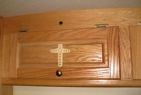
Fortravel delivered my coach with a 20 inch hi-line Panasonic color TV in the front, and a Panasonic 13 inch TV in the bedroom. This has been quite satisfactory over the years with just a couple of problems. Early-on, but not recently, the sound would lose volume for a while. Also there is a periodic color banding, apparantly from magnetic disturbance from the radio speaker just behind it. I don't know why this is just sometimes a problem. The only other problem I have seen is the lower right corner has a somewhat soft focus. The result is it is difficult to read all the satellite guide information. As analog television is going away February 2009 to be replaced with only digital signals, I decided it was time to improve the TV's, front one first. I had the advantage of seeing photos of a number of similar conversions by fellow Foretravel owners. These were all flat panel LCD TV's ranging from 26 inches to 42 inches (diagonal measurement). I decided that I wanted the largest set which would mount on the face of the existing TV cabinet without inhibiting access to any adjacent cupboards. This turned out to be a 26 inch set. I started my on-line research and went around town looking at and measuring TV's of all brands. I looked at quite a few, all of which receive digital channels and will display in high definition resolution. There were several "deal-busters". Obviously it had to fit within the dimensions I had determined were the limits. This ruled out any side speaker units, only bottom speaker sets would qualify. It had to use remote control codes that my DishNetwork remote would recognize. This ruled out several of my otherwise front-runners. Vizio makes a set that seemed to meet all my needs, except that every one I saw just did not have the picture quality of adjacent sets. I initially settled on a particular Sharp unit that Costco carried, then looked up reviews on the Internet. About 60% of the reviews I read complained about inadequate sound volume and quality. I passed on that set. I then homed in on an LG model that had an absolutely beautiful picture. The on-line reviews for this one warned about very high failure rates. I passed again! I finally chose and bought a Sony Bravia TV which passed the review test, the remote compatibility test, the picture quality test, the sound test, and the size test. I am a happy camper. The only negative I have identified for this set so far is that the manual control buttons are on the top of the front frame. I had hoped for ones on the front or right edge. I can easily reach them, but will need to label the front to know what I am pushing. OK, now that I have the TV, I have to figure out what all I need to do the the cabinetry to mount it. If I simply mount it on the front of the existing cabinet without modification, the side cabinet door will not open. I need to cut the existing cabinet down by about 3 1/2 inches. This is enough to easily clear the side cabinet door, but not so much that it exposes space past the side paneling. I have no idea what is involved in removing this cabinet, but if it went in, it has to come out! I removed the front bezel, then removed the TV. Inside the cabinet
I could see many screws and started removing them. Before going too
far, I removed several wires, the switch for the local TV antenna booster,
and the booster itself. Removing the cable from the IR remote control
extender left everything clear. I finally found the last hidden screw
and the cabinet came out cleanly.
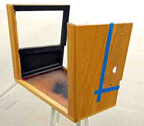
The cabinet is anything but rectangular. The entire cabinet is
tilted downward and the face is angled towards the center of the coach.
I measured all the angles and decided how to cut off the front edge.
The first cut across the bottom was a 4 1/4 inch 90 degree cut. I
then tilted the saw blade 8 degrees and very carefully adjusted the saw
fence to align the blade with the end of the first cut. I then cut
the side. The second side was cut the same way by again carefully
aligning the angeled blade to the end of the bottom cut. It all worked
fine, leaving me a smooth front of the sawed off cabinet. The front
frame I cut off incuded 3 1/2 inches of side and bottom paneling.
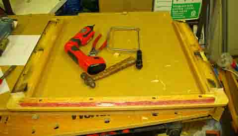
I carefully removed these panel pieces using a hammer to break the glue
joint, then a chisel to clean up the glue and wood splinters from the edge
of the frame. A little careful coping saw work removed pieces where
there would be interference at assembly.
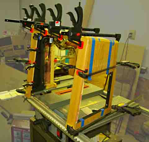
I assembled the front frame into the cut-off cabinet and brought out
all my wood clamps. After figuring out how to clamp it all, I glued
all the surfaces, assembled it, and reinstalled all the clamps. The
dried assembly looked quite good, but did have some minor gaps and irregularities.
I used some oak shaded wood putty and filled all the joints. This worked much better when I started using masking tape on both sides of the joint, and puttied between them. This not only kept the putty from filling the surounding grain, but also left it high by the thickness of the tape. Upon sanding, the joint was flush, even if there was a little shrinkage. I also cut the top out of the original bezel, which will no longer be used, and used it to fill in the open top of the frame. I thoroughly sanded all faces of the cabinet both to remove most of the original finish, and to smooth up all the newly glued joints. I then applied 3 coats of clear lacquer. This provided a finish I was unable to tell from the original. The modified cabinet re-installed just the reverse of its removal.
I had to drill only one new hole to screw the front of the left side up
to the ceiling to replace one that was in the area that was sawed off.
Fortunately this screw hit an aluminum frame member, and had all the strength
of the original.
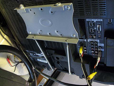
The mount I bought to actually hang the TV is a 2 piece steel unit.
One piece mounts to the holes on the back of the TV. The other is
mounted to the wall, or in my case just inside the cabinet. The TV
will then just hook to the stationary mount, and then clamp in place by
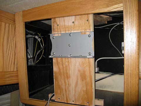
tightening two screws. This mount is 7/8 inch thick. As the
rear of the TV is somewhat smaller than the front, I decided to mount the
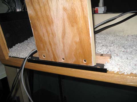
fixed part 1 inch behind the front of the cabinet. To do this, I
mounted a vertical piece of oak to the base of the cabinet. The top
of this oak board is attached to a board that runs forward to an aluminum
roof frame member. The fixed half of the mount is screwed to this
oak panel. This all gives me the structural stability I need to keep
the TV safely and stablelly mounted. I made one small modification
to the mount, so the screws I tighten after hanging the TV actually tighten
the mount halves to each other, instead of merely providing a pin that
prevents the TV from lifting off.
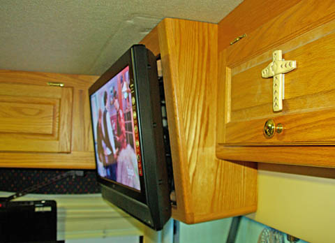
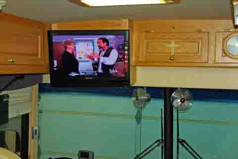
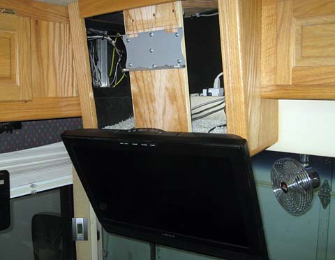
I am very happy with the final result. The TV looks much larger,
even though the picture is only a little bit higher, it is a full 6 inches
wider. The picture quality is excellent, and even the satellite guide
is easily readible. When using satellite, my program selection is
the same as before. I do not have a high definition satellite antenna
or receiver in the motorhome. However when watching TV from the rooftop
local antenna, I can now pick up all the digital chanels, including high
definition ones.
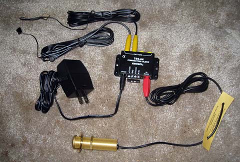
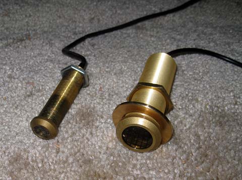
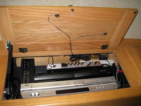
My Foretravel came stock with an infrared remote control extender. This consisted of a small IR receiver mounted on the surface of the center front cabinet above the door, a connector block, and a pair of emitters which were fastened to the receivers inside the closed cabinet. In operation, the receiver would pick up the remot control signals and relay them to the emitters, which in turn would activate the controlled items. Unfortunately, this system deterioated with time, to the point that it did not work at all for the last couple of years. I would just open the door to the equipment cabinet when I wanted to watch satellite TV, or use the VCR/DVD player.I decided it was time to fix this, so I went on line, and after a bit of research, selected a complete new system from the same manufacturer as the original equipment. In the time since my motor home was made, the company has made a number of new products to solve some of the developing problems. The system is designed for home stereo systems where the equipment is housed in cabinets, just like my situation. The system I selected is designed to reject interference from LCD TV's and compact fluorescents (CFL) bulbs. My lights are not CFL's, but are very similar as the balasts run at a very high frequency, just like CFL's. The kit I bought included the receiver module, the connector block, a power supply, and 4 emitters. The receiver is larger than my old one, mounting in a 3/4 inch hole instead of the 1/2 inch for the original. Other than that, the kit is very similar to my original parts. The only functional change I made was to use the included power supply to provide the 12 volt power for the unit. Originally the unit was wired in to the house 12 volt system. I worried about that as the voltage can reach 14 1/2 volts during charging and the manufacturer specifies a regulated supply between 11.5 and 13.0 volts. The only time I will use the extender is when my TV is on, and as that is 120 volts also, power will be available.
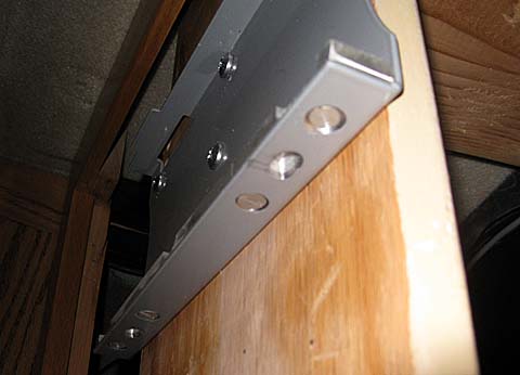
I had to remove the TV to gain access to the area where the original connection box was mounted. While it was off, I decided to make a couple of minor improvements in that area. When I am mounting the TV, the audio and video cables are fairly easy to attach, as they are quite long. The TV antenna cable is not so long and it is a real problem to hold the TV high enough to attach it. The power cord is difficult also, as I have to plug it in far away from the TV, and that makes the TV very hard to hold. I solved the problem by mounting a short length of 1/2 inch angle iron to the bottom of the TV cabinet. This allows me to temporarily hang the TV from this angle while attaching the various cables. Once the cable are all attached, I lift the TV off this angle and hang if from its regular mount. As I drive, once in a while I can hear a dull ratteling in the TV cabinet. I think this is the cables bouncing on the wooden floor of the cabinet. While the TV was out, I lined the bottom of the cabinet with carpet. This should eliminate the rattle.
Addition of 3/6/2016 Upgrading to a Hi Def Receiver with DVR For some time now I have been looking at a replacement Dish Network satellite receiver for my motorhome. The receiver I have been using for many years (model 311K) is a basic, standard definition, single TV receiver that has been working very well. There is a newer series of receivers (VIP 211K and VIP 211Z) which offer a couple of significant advantages over my current one:1. The output supports high definition 2. By plugging in an external hard drive and paying a nominal one time fee, they become fully functioning DVRs. After I decided it was time for me to upgrade, I spent quite a bit of time reviewing the two variations of this receiver. The 211K is an older receiver with more capability than the newer 211Z. They are both easily available and cost exactly the same. In the end I decided on the 211Z. Here are some comparisons: The 211K has many forms of output to the TV, including HDMI, Component video, Composite video, Svideo, analog audio out, digital audio out, and RF to supply the antenna input of a TV. It also includes an antenna input (and tuner) for local over the air reception, ethernet, phone and USB ports.The 211Z has only an HDMI and composite video and analog audio outputs along with an ethernet and 2 USB ports. The only missing output on this model that I need is the RF output. I can replace that function with an external RF modulator. It is also considerably smaller and lighter than the 211K. The main deciding factor for me was the power consumption. Even though I really like the features of the 211K, it draws over 30 watts whether it is on or off (satellite receivers never really turn off). The 211Z draws just 11 watts. I read numerous reports about the 211K running very hot, even to the point that it would fail if its cabinet door was not left open. That, the smaller size, and the newer technology were the deciding factors for me. My old receiver had many of the same non-hi def outputs as the 211K, including the off the air receiver. I never used anything but the analog outputs for the front TV, and the RF output for the rear. In my new installation, I feed the TV with an HDMI cable as needed for the hi-def programs, and the rear TV is fed from an external RF modulator, which is driven by the composite a/v ports. The really exciting part about this new receiver is its ease of conversion to a fully functioning DVR! I plugged in a 1 TB portable hard drive, followed the on-screen instructions to format it, and after rebooting, the receiver had all the new DVR functions. I am really pleased with the final results. The picture is beautiful, the responsiveness of the menus and other functions is much faster than my old receiver, and of course, the DVR is incredible to have in my motorhome! Another unexpected improvement was the better response with the IR repeater system described above. While it worked OK with the old receiver, the response was slow. You had to hold the remote button down for about a second, or it would not respond. Also on some functions if you held it just a little too long, it would execute the functions more than once. The performance with my new receiver is prompt and immediate. There is no tendency to get multiple hits for one press.
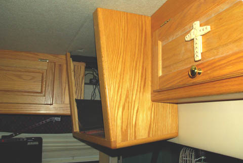
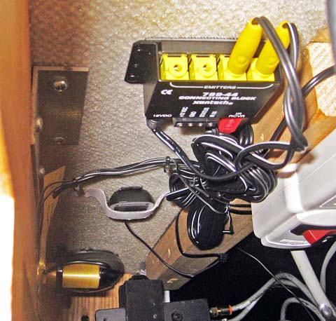
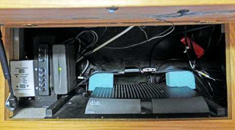
The
installation was quite simple. The receiver is smaller than the
old one, so it fits easily, and the new RF modulator is mounted to the
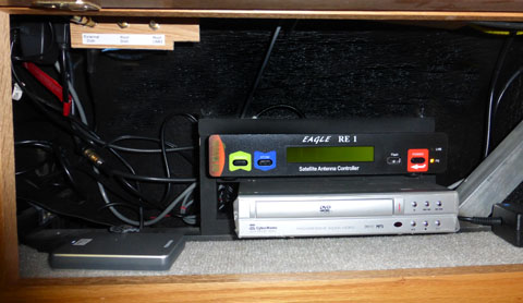
left vertically next to the antenna switch. Yes, that is an automotive seat belt holding the receiver in place with a couple of blue foam blocks to cushion the receiver, and to give the belt a good angle to hold it down. On the right is the adjacent cabinet showing the DVR hard drive at the lower left. It also shows the controller for the rooftop dish and the DVD player. I no longer carry a VCR.
|
||||||||||||||||||||||||||||||||||
|
Dick Mason, Prescott, AZ 4/15/08
|