Solar Panel Installation
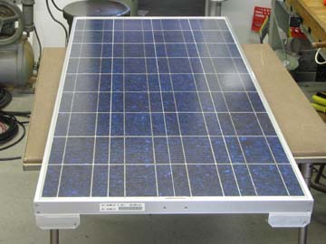
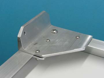
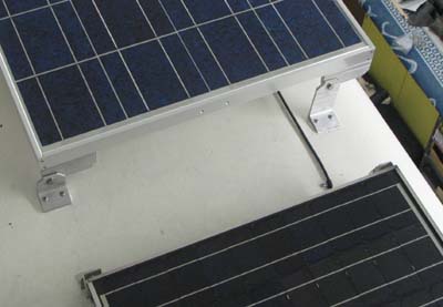
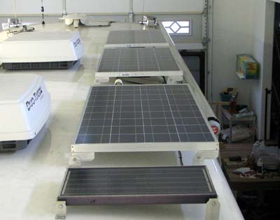
When we first bought our Foretravel, I decided I wanted to install a solar system to reduce our dependency on the generator. For several reasons (time, money, procrastination, etc.) I let four years go by without adding the solar system. Recently (early 2005) we spent several days at Quartzsite with a camping group, and I again went around pricing panels and controllers. I was shocked at how much they had gone up in four years. In 2001 Quartzsite had the best prices I could find, beating the prices I could find on the Internet. Now they seem to be about $100 per panel higher than the Internet prices! I did a lot of research and decided on three Kyocera KC120-1 panels at 120 watts each, and a Solar Boost 2000E Maximum Power Point Tracking controller. This controller always operates the panels at the voltage which yields the highest wattage, and using a switching type power converter, converts this power down to the proper charging voltage for the battery. It is kind of like a DC transformer. The net result is that you gain up to about 30% charging current compared with a conventional controller that merely hooks the panels up to the battery, with an on-off switching action. I have been told to expect realistically about an overall 10% improvement. There is a worldwide shortage of photovoltaic panels and a lot of outfits are out of stock. Northern Arizona Wind and Sun had the best prices I found for the equipment I needed, and by sheer coincidence I called them the day they received a new shipment of panels. Although they had all been promised, someone no longer needed theirs and I was able to get mine. I drove the two hours to Flagstaff and picked them up that day. My first project was to design and build the mounting brackets. As I was mounting the panels level along one edge of our crowned roof, I needed to make the outside bracket taller and move it in from the edge of the panel some to avoid mounting it to the sharp curve at the edge of the roof.. I used a length of 4 inch aluminum channel (left over from Betty’s lift project) and cut all the brackets from it. The panel half of each bracket is screwed through two of the factory
holes on the side rails, but I could not drill holes in the end rails without
voiding my warranty. I decided to clamp to that rail.
I had decided on the routing of the wiring from the panels to the controller and then to the distribution points for all the house 12 volt power, which is closely connected to the batteries. The Solar Boost manual emphasized the need to minimize voltage drop for the best efficiency. They suggested a maximum of 0.42 volts total drop through wiring. Even though a single 10 gauge wire will carry the 25 amp maximum current from the controller, the voltage drop would be excessive. I ended up using 10 gauge wire from each panel to the controller, and 2 gauge wire to the battery area. I used short 10 gauge pigtails to connect to the controller. This calculated to well under the .42 volts drop. I drilled a hole through the roof into the compartment behind the electrical
monitors and sealed a piece of PVC pipe into it with silicone sealant.
The panel wires were fed through this pipe and were sealed with silicone.
This pipe extends up slightly from the roof and is under a solar panel.
That and the sealant should assure no leakage.
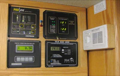
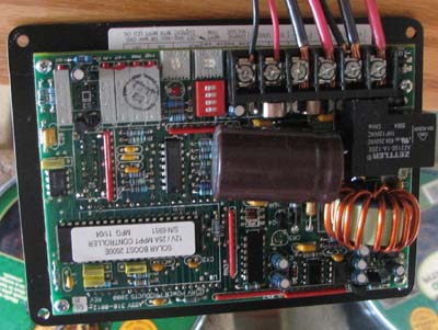
Almost as an afterthought, I decided to mount a small 20 watt solar panel I had removed from a previous motorhome and use it to trickle charge the starting batteries. It uses no controller. I mounted two pin jacks on the monitor panel. One is connected to the solar panel, the other to the starting battery. I have a small U jumper connecting them. If I want to disconnect the panel or measure the current I can do it at these jacks. The Solar Boost controller is self-contained on the rear of the panel instrument. Mounting this posed quite a problem. I needed to remove the CO detector from the monitor panel and re-mount it elsewhere, then I needed to modify something to gain enough additional mounting area for the controller. The AC power monitor supplied by Foretravel had a much larger mounting
plate than was really needed. I cut off about 1/4 inch each from
the top and bottom of this panel. This allowed space for the controller
below it. I made an oak frame and mounted the CO detector on the
edge of the pantry just inches from its original location.
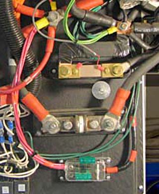
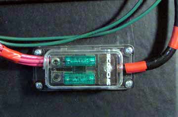
Running the 2 ga. wire was quite a challenge. I ran two lengths of this and the temperature compensation probe wire through a wiring channel running the length of the main storage compartment, then over the gray water tank to the curb edge, up through the floor, alongside the ice maker, up in the hollow left wall of the pantry, and into the monitor compartment. Here a length of 10 gauge wire is attached to each of the wires using split bolt connectors. This is the maximum wire size the controller terminals will accept. At the other end, I mounted a dual 30 amp fuse block I found at Walmart.
It accepted the #2 wire on one end, and 4 lengths of #10 wire I used to
connect to the positive distribution point. The second fuse serves
as a spare. The negative cable connected directly to the negative
distribution point.
Although I measured good voltages from each panel while parked in my motorhome garage, it obviously was not enough to register a charge. The first time I pulled out onto the driveway it was overcast. Over the next hour or two we occasionally had hazy sun. I monitored the panel output and the controller output half a dozen times during that period. I saw a minimum of 4.1 amps panel current with 5.3 amps controller output, and a maximum of 12.3 amps at the panel with 14.1 amps at the controller. The lowest “boost” I saw during this period was 12.5% and the highest about 30%. I am very pleased with the installation and preliminary results and
am anxious to get out on the road and try it "for real"!.
|
||||||||||||||||||
|
Dick Mason, Prescott, AZ 2/11/05
|