Phone, Network, and TV Wiring (done in 2002/2003)When we ordered our manufactured home in late 2002, we decided to order 5 telephone jack locations without the wiring. I figured I would do the wiring myself. As time progressed, my plans expanded considerably and the final count of what I wanted was 10 jacks in the house and a number of additional ones in my garage, shop, and motor home garage. These jacks were to include not only the telephone, but also TV and computer network wiring (Cat-5). When the house
arrived, I discovered that the manufacturer's installation of the phone
jacks consisted of a standard plastic electrical box with a hole
drilled in the bottom end. Through this hole extended a
length of
1/2 inc PVC conduit which passed down through the wall, the floor, the
insulation, and the moisture barrier. This way wire could be
easily pushed up to the box. I quickly found that all the
wires I
had decided to run would not fit the 1/2 inch conduit, and the
termination of so many wires would not fit a closed electrical box, so
in addition to adding 5 new outlets using 3/4 inch conduit and low
voltage mounting rings, I replaced the conduit and boxes on 3 of the
existing ones. The two remaining outlets were fine,
as I
was only planning on phone and Cat-5 wires in these two over-counter
locations.
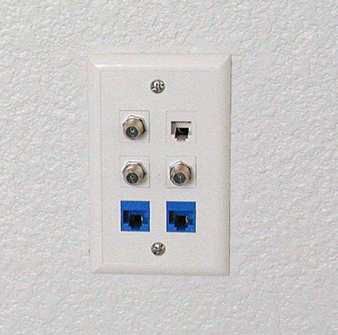
The low voltage mounting rings have the mounting shape and
size
of an electrical box, but have no box. This allows
the
wires to use the entire thickness of the wall for their bends and
service loops. This is not a problem, as these are all low
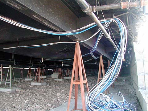
voltage devices, and the building code allows open runs of these wires. After several days of crawling under the house, I had all the wires run. These were left under the house in a large bundle for the time being. I had decided on
having a "master connect panel" on the garage wall, so all the wires
would terminate somewhere on this panel. This posed a
problem, as
the normal manufactured home is installed 2 to 3 feet higher than the
garage, and has several steps coming down to the garage. As
Betty
had a severe case of Rheumatoid Arthritis and could not climb steps, I
had the contractor lower the house and raise the garage levels from
normal so they were level with each other. We could now walk
easily between the house and garage. Normally I would only
have
had to drill through the wall below the house and above the garage
floors. With the floors level, I could no longer do that.
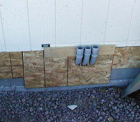
Instead, I mounted three lengths of 1 1/2 PVC conduit with
sweeping bends at the bottom. These were positioned so the
tops
would extend through the poured concrete garage floor and the bottoms
would be accessible under the house. NOTE! Whenever
you do
something that is so final, be sure to make the capacity handle the
most you think you could possibly need and then DOUBLE IT! I
thought I had plenty of excess capacity in these conduits, but ended up
really packing them with wires.
After construction was pretty well
completed on the garage, shop, and motor home garage, I completed the
wiring for the house by running all the wires through the conduits and
up onto my patch board. I also ran a number of wires
throughout
the garage, shop and MH garage. All this wiring was done over
the
ceilings using runs of 1 1/4 inch PVC conduit. These ran to
my
shop, to the back of the garage, and to the MH garage. In the
MH
garage, I left an access panel on the wall where the conduit ended and
ran two additional conduits down to the wall below feeding both the
garage and MH garage, and to the center of the MH garage ceiling.
Here I made another access cover and ran two more conduits to
the
center of the right hand wall (looking from the driveway), and to the
left rear corner. The first fed a jack that was close to the
utility bay of the motor home, and the second fed down the common
shop/MH garage wall and fed jacks on both sides. The access
panels were used to feed a wire from one conduit into the correct other
conduit. Many of these jacks were phone only. I
sent TV
(two wires) and Cat-5 only to my shop work bench and the utility jack
by the motor home.
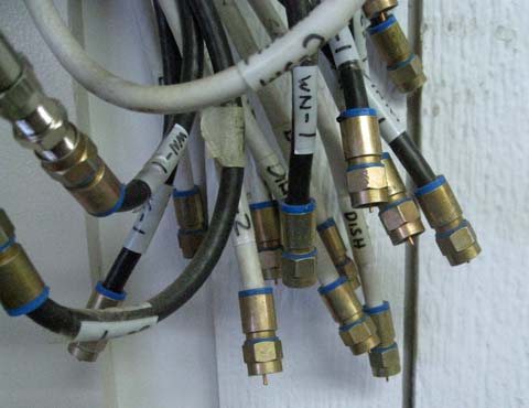
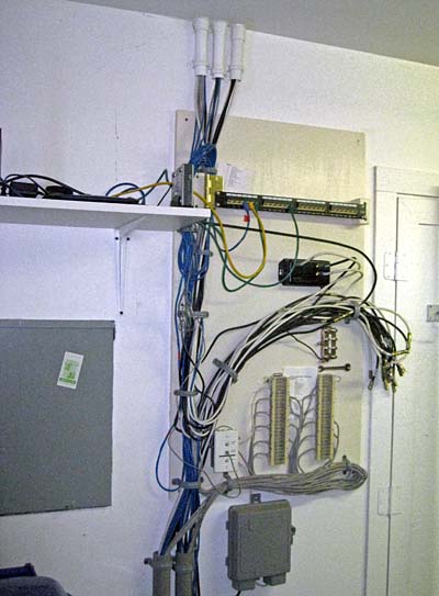
I bought a network distribution strip consisting of 24 Cat-5 connectors on a metal frame. Each connector has punch-down terminals on the rear. I mounted this on a hinge and connected my 14 network cables to the first 14 connectors. I can now plug in Cat-5 patch cables from my router into the appropriate connectors to feed the desired house jacks. I originally subscribed to cable TV and convinced the installer to bring the cable directly into my garage instead of having an unsightly box on the outside of the building. He also gave me an 8 way splitter from the cable and verified his signal was strong enough to drive all 8 positions. The TV cables were just brought to the area in a bunch. The appropriate ones attached to the splitter and the others just sort of hung there. After I changed to satellite TV the splitter was no longer used and the main function of these cables was to deliver the dish antenna signals to the correct locations and to connect multiple TV's to the receivers. This was all done with barrel connectors between cables, so now the wires just hang in their bunch with several connected as needed. It is not too pretty, but very effective.
When the cable company stopped carrying the Flagstaff station which I liked very much for the news, I installed a large TV antenna in the MH garage attic and fed it to the board. As the signal was poor, I added an amplifier, but the results were only marginal. It really doesn't matter, as shortly later, the Flagstaff station stopped producing their own news and just mirrored a Phoenix station. I get those! I used two standard telephone punch blocks for the phones. I did not want any daisy-chaining of the phone wiring, as I have had problems in the past that were almost impossible to locate. Each of my 20 phone jacks has a wire running from the jack to the punch down block. I wired all the jacks for 2 line capability, even though I have only one line. I was also able to talk the phone installer into putting his box in the garage. I have no messy cable or phone wiring on the front of the house. This is also much more secure. When I converted to a VOIP phone (phone service over high speed Internet), I added a junction box with 3 phone jacks in it. One is attached to the phone company wire, one is attached to my house wiring (the feed to the punch blocks), and the third is merely an additional phone jack for testing or adding a phone. I have a short jumper which will connect the phone company wiring to my house wiring. If I remove this jumper, as for VOIP, I can feed the house wiring from my VOIP box with no connection to the phone company.
|
||||||||||||||||||
|
Dick
Mason, Prescott, AZ 5/15/11
|