Mail Box Monitor August 2006and Updated Model September 2021
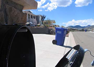
When I had the house and garages built, I ran a conduit from my mailbox to the house to allow the future addition of a wired mail box monitor. I finally decided that the time had come! I often make a number of trips out to the mailbox to get my mail, only to find it has not yet come. A friend of mine bought a wireless monitor which sounds a musical alarm when it detects a certain level of vibration in the mailbox. This is good, but has some limitations. It sometimes sets off the alarm when a neighbor opens or closes their box. (They have an area box with multiple boxes on one stand.). Also, sometimes it fails to sound when there truly is a delivery to the box. I believe they have an indicator that shows if the alarm has sounded, so if they do not hear it, they can still tell if it activated. I wanted at least the reliable equivalent of this. For my alarm, I thought of a variety of ways to detect the mail's arrival:
Several were:
There were several other more off-the-wall ideas also. I decided that to start, the most practical system would be to sense when the door was opened. After evaluating several techniques to sense the position of the door, I bought a door/ window alarm sensor switch from Radio Shack. This consists of a powerful magnet in a plastic housing, and a reed switch in another plastic housing. When the gap between the properly aligned sensors is less than an inch, the circuit is closed. When the gap is greater than that, it is open. I initially discovered that mounting the magnet and switch directly
to my steel mailbox and door reduced the sensitivity to less than 1/4 inch,
so I re-mounted the magnet on a small piece of 3/8 thick aluminum and mounted
that to the door. This isolated the magnet from the door steel, and
also allowed me to align it with the reed switch better.
I did not remember whether I had merely run the conduit before the driveway
was poured, or whether I had been smart and also run the wire in it.
Of course I found I had only run the conduit. Actually the "conduit"
I had run was really a length of 1/2 inch plastic drip irrigation feed
hose, and of course it had kinked somewhat in a couple of locations.
After fussing with my electrician' fish tape and the wire for well over
an hour, and making numerous crawling trips under the house to where the
conduit came out, I had a wire run from the mailbox to my patch panel in
the garage where I connect all my computer network, TV, and telephone wires.
I plugged this cable into my network panel connection to the utility room
and verified my connection there. All was OK. Now I had a make
or break circuit located where I want the alarm to be, that tells me if
my mailbox door is open or closed. All I have to do now is design
and build a quality alarm.
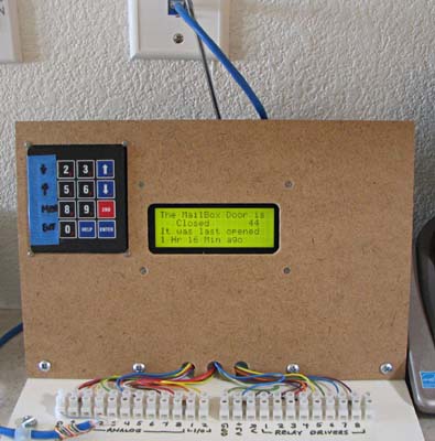
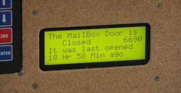
I decided to use another LCDX module like I used for my motorhome tank level monitor. This is a 4 line LCD display with a BasicX microprocessor, RAM, EEPROM, and a number of inputs and outputs. It is a bit of over-kill for this project, but at $80 it saves me a LOT of custom building. I added a jumper that converted one of the voltage inputs into a 0 to 10,000 ohm resistance input and I connected my switch there. If the resistance is at or over 250 ohms, the door is read as open, if less than 250 ohms, it is closed. So far, my implementation is in the form of my LCDX breadboard setup. This is an LCDX panel monuted to a board with a keypad, and terminal strips for all the input/output connections. After complete checkout I will mount my other LCDX panel in a small case which mounts on my cabinets. I then proceeded to write a program that would use the time the door was opened and display it as how long ago it was last opened. I started with my tank level monitor program, kept the menu structure and a few utility routines and deleted the rest of the code. I then wrote the code needed to time and display the duration since the last door closed-to-open transition. I initially had a little trouble with the timing routines which used
year, month, day, hour, minute, and second, and eventually re-wrote it
to use the seconds since midnight timer. When I see that the timer
has reset to a low number (midnight), I add 24 hours to the total time.
This seems to work, and with the variable types I have selected should
give me a maximum duration of just over 22 days. I hope I never skip
my mail for that long!
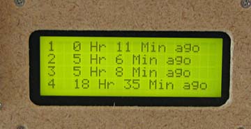
During the course of developdment, I added several additional functions: If I hit the DOWN arrow key, it displays the times since the 2nd, 3rd, 4th, and 5th last times the door was open. Of course the main display shows the time to the most recent opening. These extra times help assure me that no one has opened the box other than the mailman. or at least that the box was only opened once since I last accessed it. New menu items let me look at the raw minutes in this history log, and to set the running timer to 10 times real time. This helps me troubleshoot various functions without having to wait nearly as long. I also added an audible alarm that gives a warbling tone for several
seconds when the door is first opened. There is a menu item to turn
this on or off.
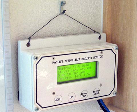
So far, the alarm has functioned flawlessly. It has always properly shown me how long it is since the door was last opened, and I have yet to make an unnecessary trip to the mailbox. Update of 9/20/07
I used one of the interim oak mounting frames I had made for the motorhome tank monitor project. This was a double frame which I sawed down to a single frame. I then did the cardinal sin of cabinet making: I painted my beautiful oak frame! I made an aluminum front panel similar to, but less complex than my motorhome tank monitor. After making another push button circuit board, again like the one in the tank monitor, and painting the front panel, It all went together quite easily. I printed a front panel on white paper, laminated it in plastic, and
attached it to the front panel with double sided tape. That completed
my monitor.
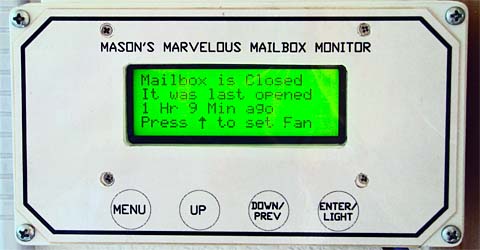
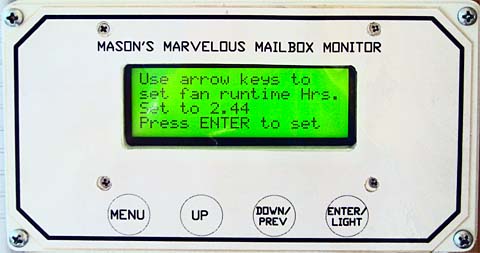
Since I installed the whole house fan, I have felt I should have a timer for it. As I never got around to buying and installing one, I had a thought! My mailbox monitor is a fairly powerful computer based controller, which is doing very little in the way of using the power built into it. I decided to add a fan timer function to it. I actually had to add very little additional code to add this function. I had to write modules to input my desired setting, a few lines of code to actually do the timing, and several new display screens. I also had to add a relay to actually switch the fan on or off. I used the 2 remaining spare wires of the Cat-5 cable to connect this relay to the fan switch. The connector for the Cat-5 cable and the fan switch are only a few inches apart, with no wall stud between them, so the wiring was simple.To start the fan function, I press the UP key. This takes me into a time selection screen. In setting the time, the UP key increments the run time in 1 hour steps. The DOWN key decreases it in 15 minute steps. Hitting ENTER sets the timer to the selected time and starts the fan, which then continues to run for the set time.
Update of 5/1/11 Last season I had several occasions where I wished I could set the timer for more than 10 hours. Also, on the few times I have wanted to shut off the running fan, I found it somewhat awkward to continually decrement the time by 15 minute steps to clear the timer. I decided to correct these two factors. With a very small software modification, I increased the maximum time to 16 hours, and wrote a routine which senses a double-press of the down button while in the time setting mode. This clears the fan timer.
NEW MODEL September 2021 My
monitor is now 15 years old,
and is showing its age. A couple of the buttons are now
intermittent and their labeled overlay is cracking. The monitor
itself periodically "self resets". This totally blanks all the
data and without examining the previous openings, it is impossible to
tell if the time shown is since the last mailbox door opening or the
last reset. Another problem is that it requires a serial port for
programming. Serial ports are almost non-existent on modern desk
top and laptop computers. As part of my looking for another Covid-at-home project, I decided to build a modernized version of this monitor. The original monitor was based on the Basic Stamp, one of the first small single board computers, and the LCDX version was a unit consisting of the board and an already integrated display of 4 lines of 20 characters each. For this version I decided to use an Arduino board, a single board "controller" about the size of a credit card. There are numerous displays available to easily connect to this board. Instead of the structured BASIC programming language of the LCDX, this uses a subset of the C++ language with minor variations. I started with a desktop
breadboard consisting of an Arduino Mega, a knob driven encoder, and a
4 line display very similar to the current one. With this setup I
was able to write the major portion of the code required for the
mailbox timing portion, but quickly decided that I need to update the
display as well as the computer. I ordered a 2.8 inch (diagonal)
color-touch screen display for $15. When it arrived, I changed
the display library and had a much more capable display. I
decided to not use the touch screen capabilities. 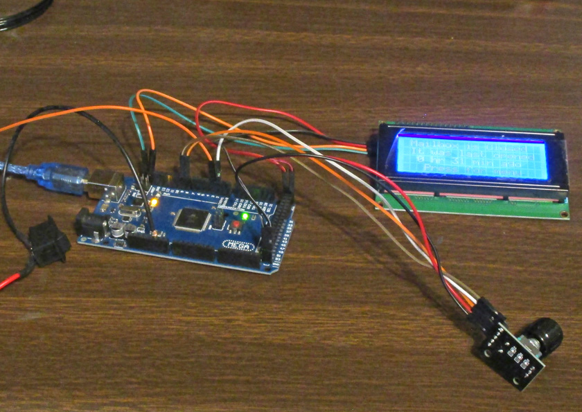 This is my initial breadboard setup, which I used for the early programming. Wiring was very simple, with only 2 leads plus power to drive the display, and 3 leads plus power for the encoder. The switch simulating the mailbox door takes only 2. The USB cable provides all the power required and connects to the main computer for programming. 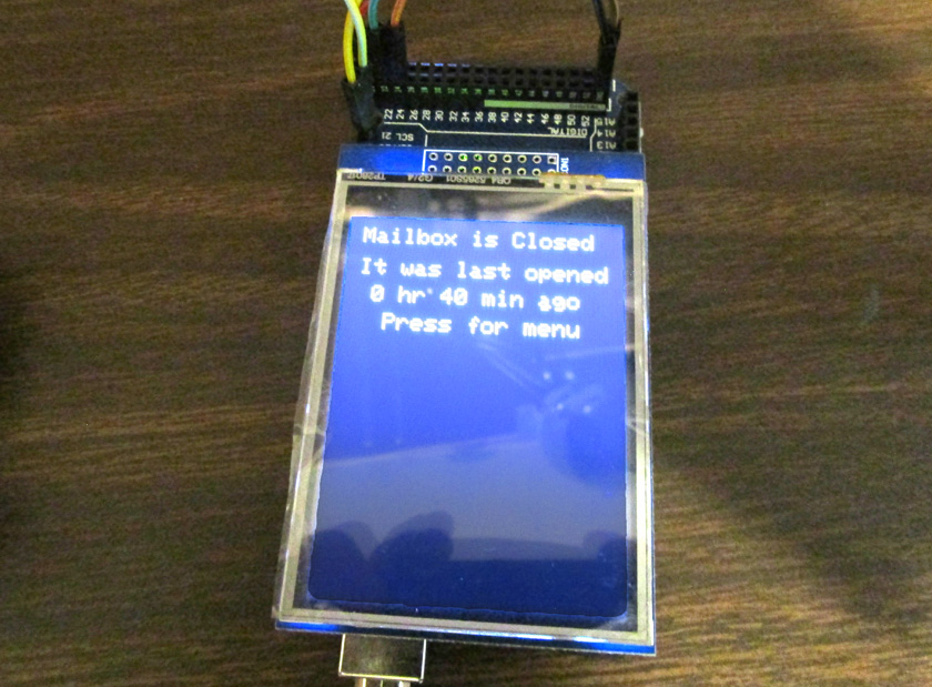 My new display is configured to plug directly into either an Arduino Uno or an Arduino Mega. Here it is plugged into a Mega. The Mega has many more inputs and outputs than the Uno, and is about 1 1/4 inches longer. This exposes a number of I/O pins for the other connections required. After getting it running with
the new display, I designed and 3D printed a case to hold all the
pieces, including a relay board to use for the fan function. I
completed adding the fan function which is much simpler to use with the
rotary encoder to do all the setting. A menu selects the basic
functions along with a couple of setup and troubleshooting ones.
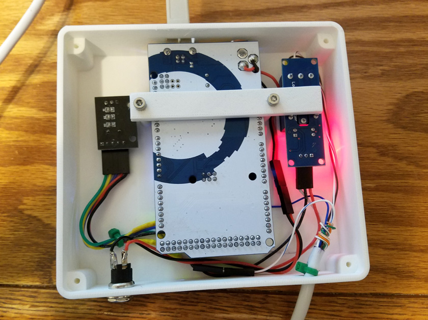  This is the monitor installed in its case, ready to turn over and run. The relay board has a "handy" red LED to show when it is powered up. It is so bright that it shows through the case, and was first on my list of changes to make, until I decided to replace this unit before even putting it into service. I replace the replacement monitor with a yet better replacement:
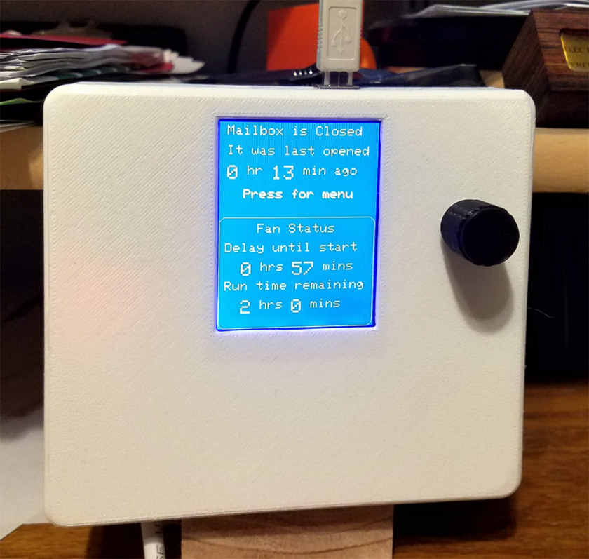
When I finished building this and briefly put it into service, I just wasn't happy with it. The display had a lot more flexibility than the old 4 line one, but when it was necessary to refresh the screen it was very slow. When you need to change much of the data on the screen, it is best to blank, or refresh the whole screen and then write the new data. Merely writing the new information results in a combination of the old and the new data. Refreshing it probably took at least a second for the line between the old and the new information to slowly move down the screen. This was not really bad when changing modes or adjusting things, but when the program updated things such as the change of a minute or hour it was very distracting. I decided to try a different display. I found a somewhat larger (3.5 inch vs. 2.8 inch) display for a whole $3 more and bought it. It was described as a very fast display and had more basic resolution than the previous one. What a difference! Instead of a slow wipe down the screen when refreshing, it merely blinked quickly! I was very happy. Of course with a new larger display it meant that I had to design and 3D print a new case. This was not bad as I love doing this kind of designing. This larger display covered all the extra sockets of the Arduino, so I had to get clever with some angle pins to make my connections to the outside world. It, like the previous display plugged directly into the Arduino, but this one requires the larger Mega, which I had already chosen for the first revision. I also thoroughly destroyed the red LED on the relay module which was so annoying on the last version. The software transferred over with very few changes other than a different display library. I improved the graphic design a lot from the last version and actually use some of the colors in the display. 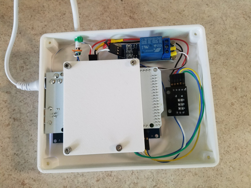 This is looking at the back side of the completed third model. The Arduino Mega is the white circuit board, and you can see the black edge of the display beneath it. The rotary encoder is on the right and the relay module (without the red LED) is on the top. 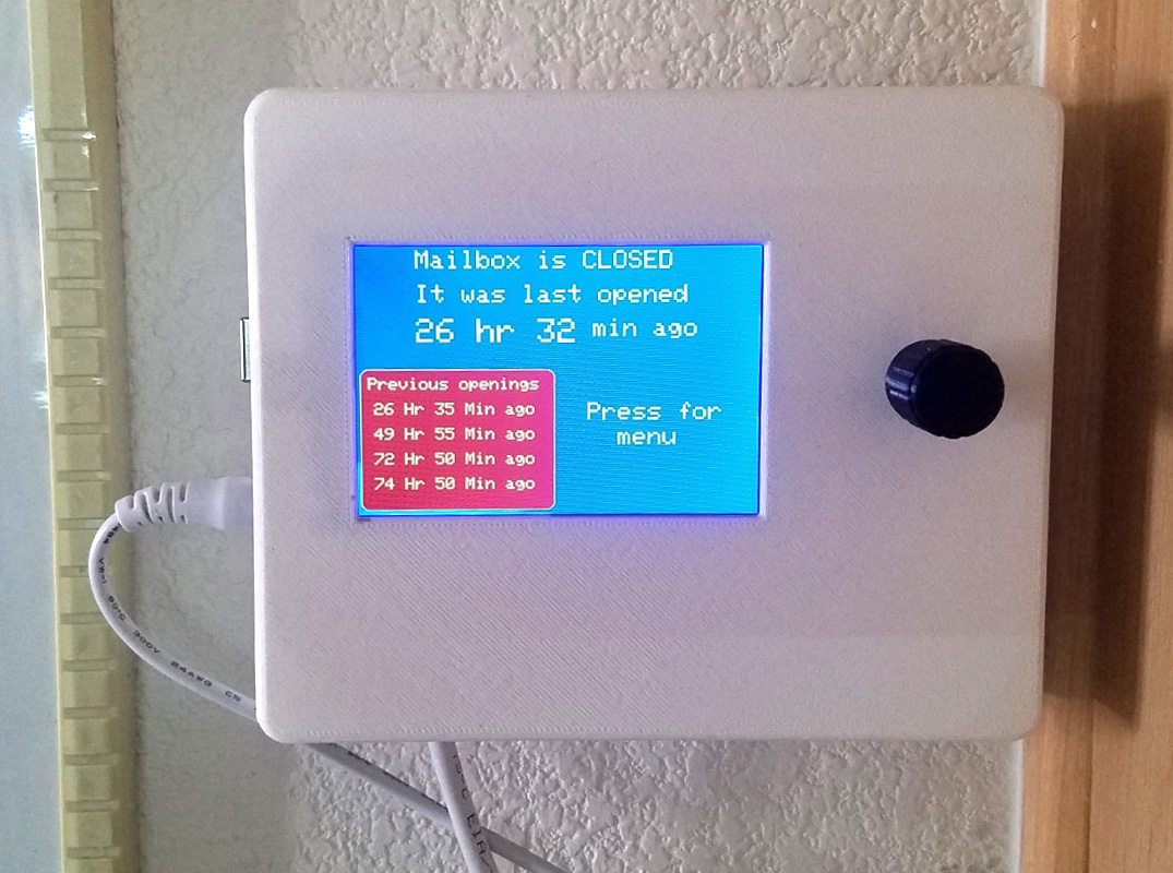 This is the completed and installed monitor and fan timer. When in the fan mode, the information in the red box is replaced with the fan status. The menu allows setting the fan, both a delay before starting and the run time, a separate selection to immediately cancel the fan, a color selection menu, a choice of faster than real times for troubleshooting, and a calculator to allow fine tuning the timing to compensate for a slightly off frequency crystal (they are not always perfect!). Note: The picture shows a distortion (a moirè pattern) in the background caused by the pixels of the camera and the pixels of the display not lining up. When actually viewing the screen it is smooth and clear. This third version of the monitor has been in service now for several months, and has worked perfectly, although I will need to wait for next summer to test the fan functions in actual practice. This has been a fun project which has forced me to freshen up what few programming capabilities I have and create a useful replacement for an ailing instrument.
|
||||||||||||||||||
|
Dick Mason, Prescott, AZ 8/31/06
|