|
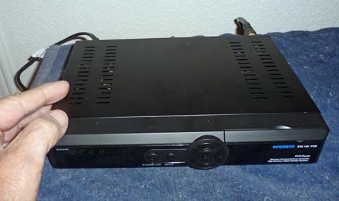 |
The Openbox S10
receiver is really quite tiny, but has a lot of features.
Yes, Openbox is
truly the brand name, not the condition of the packaging.
|
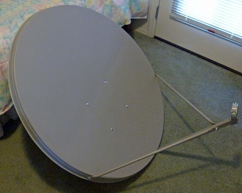
| The
36 inch (90 cm) dish actually measures 35 inches wide by 39 inches
high. This is much larger than the common Dish or DirecTV
dishes, which work with very high power satellites. The LNB (low noise blockconverter), the actual antenna, mounts on the bracket on the right. The dish gathers energy from the satellite and focusses it all on the LNB. |
 |
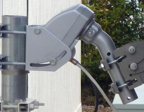 |
The
motor mounts between the post and the dish. The setting of
all the angles is quite complex, and must all be exactly correct for
the dish to accuractly track the arc of satellites. All the geostationary satellites are located above the equator at an elevation of about 22,236 miles. This is the altitude where the speed of orbit exactly matches the earth's rotational speed and the satellites all appear to be stationary in the sky. All these satellites are in a very narrow ring around the earth called the Clarke Belt, and the part visible from any given location is often referred to as the satellite arc. As long as the dish accurately follows this arc, you can receive all the satellites that broadcase a strong enough signal for your dish and LNB to receive. In all, there are about 300 geostationary satellites around the world. Of course these serve many purposes in additon to TV and radio broadcasts on Ku band. From my locatioin in central Arizona, I should have access to up to about 3 dozen FTA satellites. |
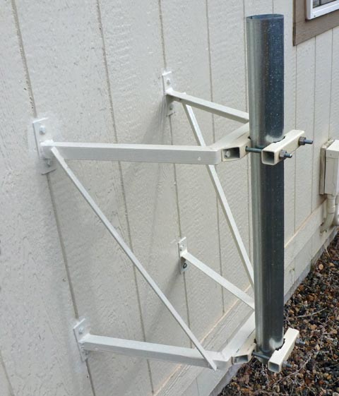
For proper operation, the system needs to be mounted on
a very sturdy, totally plumb post. This can be a post set
into concrete in the ground, mounted to a wall, or mounted on a
roof. I decided to build a very sturdy mount to fasten to the
south facing wall of my house, which fortunately is the rear.
It mounts into two adjacent studs and is designed to allow a very a
accurate alignment of the post. From this position I have an
unobsructed view practically from horizon to horizon. This
should allow me to receive all the possible satellites.
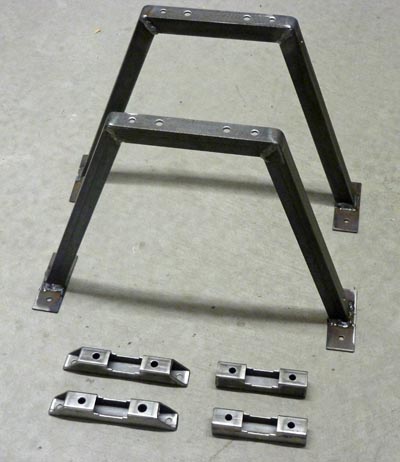 |
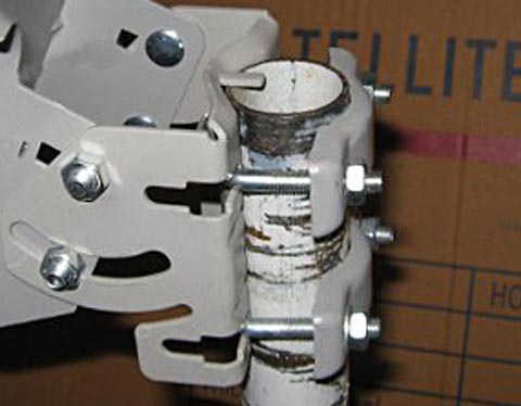
These
are the raw brackets I made. The angle iron pieces are the
main
structure. The pieces at the bottom bolt to the framework and
clamp the post. They allow a certain amount of adjustment,
which
along with selective shimming allows the pole mount to be made
absolutely vertical. After mounting the framework, I came back and slotted the holes in the base clamps to allow a wider range of adjustment than the oversize holes allowed. Even though the frames allign very well here, they were about 1/8 inch out of alignment once I mounted them to the house. |
| I
built the mount to be very stable. It mounts to wall studs
with a mounting pattern 16 inches wide by 18 inches high. The post mounting brackets were designed to be adjustable left and right and able to be shimmed in and out. After about an hour of fiddling, I got the post so there was no visible difference in the bubble as I rotated a high quality level around the post. The post itself is a length of chain link fence corner post. |
 |
I
initially had a problrm with the positioning motor. The first
time I used it, it drove to the far east limit, and somehow crossed
over the limit so it could not be driven back. After about a
week
discussing the problem with the vendor (who apparently had no idea of
what I was saying), I decided it was simpler and less frustratiing to
void the warranty and open the motor assembly to fix it
myself.
It now works correctly, and hopefull will for more than the 1 year
warranty I gave up. I am still worried about why it ran away
in
the first place, but am hoping it was a deficiency in my original setup
of all the parameters in the receiver.
NOTE of
2/5/12:
I lost that round. After I repaired the motor, it worked
great
for a while, then it again ran into a hard limit. With
additional
knowledge of how the receiver and the motor communicate, I now realize
the problem always had to be in the motor. I had thought I
might
have allowed the receiver to create the error by a missed setting, but
I now realize that cannot happen. The receiver only tells the
motor to go to a specific satellite location. The motor keeps
track of where all these positions are and where it currently
is.
It then drives to the correct location and stops. The
receiver
has no action after issuing the original command.
If the receiver were to tell the motor to go beyond its internal
limits, the motor would stop at the limit. Something in the
motor
(such as a stuck relay, or the electronic
equivalent) is causing the motor to run away without the motor's own
electronics being aware of it. I have now ordered a
replacemt motor which an expert I talked to claims is a higher
quality one, and for less money! Oh well! ADDITIONAL NOTE:
I just heard from the vendor after I wrote a note describing my various
problems with them. In it they said they are sending me a new
motor! I will now have a back up.
One nice thing about the FTA systems is that the LNB and
the motor all operate using only the RG-6 coax cable used to bring in
the signal to the receiver. My C-band had a huge cable
consisting of 2 runs of RG-6 for the C and the Ku bands, a two
conductor cable of heavy wire with the power to the actuator, and a
cable of multiple conductors to actuate the positioner and the skew
motor in the LNB. These separate cables were fused side by
side to form a heavy ribbon cable. The resulting cable was
over an inch wide by about 5/16 thick.and had to be run between the
dish and the receiver. When I first moved in here, I mounted
a DirecTV dish and ran 2 lengths of RG-6 into the house. I
removed this dish to make room for the FTA dish. Therefore I
already have the grounding equipment and two runs of RG-6 (I only need
one) in place. I need no other wiring into the
house.
During the time my motor was down, I temporarily mounted the dish directly to the post and aimed it at Galaxy 19. This satellite probably has more "in the clear" (unscrambled) programming than any other I can receive, although much is in foreign languages. This gave me the opportunity to learn how the receiver works during what would have otherwise been dead time.
After I fixed the motor, I remounted the dish on the motor, using extreme care to accurately align the dish relative to a couple of reference holes drilled through the shaft. I then set the elevation of the motor to my latitude and mounted it all. I used the receiver to drive the motor to the correct position for Galaxy 19 and then aligned the dish to that satellite. Now, if all went exactly right, the motor should sweep the arc of satellites and I should be able to tune in to any of them. Fat chance of that hapenning!
I programmed in about a dozen satellites covering the entire part of the arc I can see from here, and miracle of all miracles, I was able to receive all of them. My quality level was typically 75% or higher, about double what is needed to lock on.To finish up, I cleaned up all the wiring, re-routing the wires that originally serviced the DirecTV dish, anchoring it all in place, then I painted all the wiring on the house. Common sense, as well as hard learned experience, says the wires will not deteriorate from the sun nearly as quickly if they are painted. I had one short length of white RG-6 from my original DTV dish that I did not paint. The insulation was totally crazed, and missing in a small area where I could actually see the shielding braid. It did that in about 7 or 8 years. I painted it all, and hopefully that cable will still work OK, although fortunately it is the spare wire for this installation. The black wires held up much better, but were still weaathered where not painted. The black tie wraps (I only use black outdoors) were very brittle, and could be broken with only a slight movement with pliers.
 |
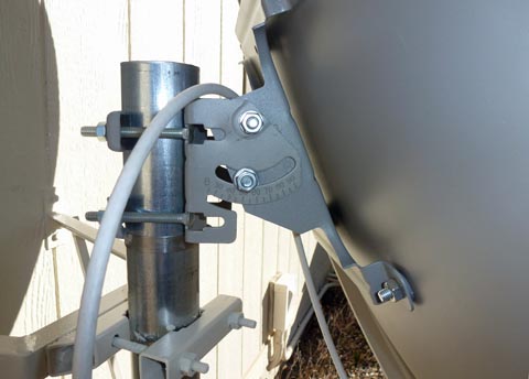
I
had a slight problem being able to mount the dish on the motor
shaft. The normal dish mounting is on a pole coming from the
bottom, which for precise alignment is clamped tightly into a formed
"V" in the bracket on the left in the picture. To facilitate
this type installation, the manufacturer formed a tab at the top of the
bracket to catch the top end of the pole and prevent the dish from
sliding down. Unfortunately, with a motor, the pole comes down from the top, and the tab prevents that. I machined the tab off, but then discovered that in the process of forming the tab, they left a bump in the metal on each side preventing the pole from resting tightly in the "V" It took about 20 minutes with a Dremyl grinder to eliminate these bumps. (This picture is from the manufacturer's website.) |
|
After the motor failure, I mounted the dish directly to the post,
without the motor. The original U-bolts that work fine on the
smaller motor shaft wouldn't fit around the larger post, so I used
carriage bolts, and it worked fine. This is where I learned just how far off the built in elevatioin scale is. When I initially pointed the dish while it was on the motor, I went through all the tables and calculations and ended up having to raise the elevation quite a bit above where it said to set it. There were enough variables that it was unclear where the error was. Now with the direct mounting, all those other variables are eliminated, and I found that for an elevation of 46.5 degrees, I had to set the scale on the dish at 58 degrees. I thought about just marking a new index point, but found that there isn't any metal where it needs to be. Oh well, now that I know it is easy to deal with. |
 |
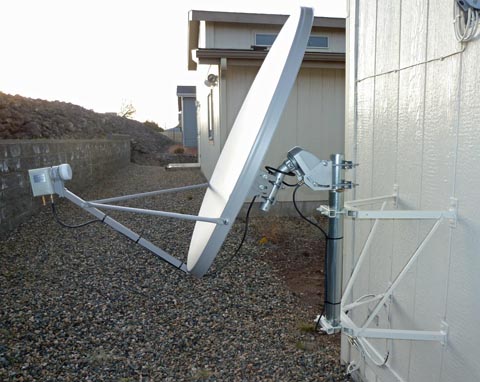 |
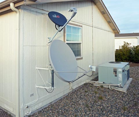
The
finished installation now has all the wires routed and
secured.
This shows how the motor is attached to the post and how the dish is
attached to the motor. This also gives a good view of the offset LNB. The dish is actually pointing about 25 degrees above the axis of the dish. The signals come down at that angle and reflect off the dish onto the LNB, which is located below the axis. The next picture shows the same type of offset on my Dish TV dish, but the offset is less, so the dish points closer to the satellite. |
| This
shows my "Satellite Wall". I use Dish Network as my primary
source of TV, and that antenna is mounted above my FTA dish. |
 |
This
has been a fun project and the results are very satisfying. I
went into this project as much for the technical challenge as for the
end product of viewing TV. I think it has been worth it on
both
counts.