Dick Mason's Electric Vehicle (EV) Conversion ProjectPart 9 Post Completion Changes and Results 12/19/08 thru 2/10/09
This is also where I will talk about the performance and endurance of the truck.
Initial
Performance Impressions
I have read a lot of experiences from other converters and the general consensus for S-10 driving was that 2nd gear would handle just about all city driving up to about 45 MPH, and then 3rd gear would handle up to freeway speeds. I was initially disappointed with the drop off in acceleration above about 35 MPH, after a very snappy start. I have found that I need to shift to 3rd between 35 and 40 to be able to keep up with traffic. Doing this results in a very satisfactory performance, and a new burst of acceleration when I shift. Studying the motor performance curves, indicates that the torque really drops off at high motor speeds. It appears that I will normally be driving below 3500 to 4000 RPM. As of this date (12/22/08) I have about 63 miles on the converted truck. I have started out driving very short distances and gradually increased the length each time. This is both for the conditioning of the batteries and for my own peace of mind and confidence building. My batteries are rated at 251 amp hours. I plan to normally stay in the top 50% of the charge, but will occasionally allow up to an 80% discharge as an absolute limit. My latest trip was a 17 mile round trip, up and down the Prescott hills, and was very successful. I recharged when I got home and the batteries were fully charged in less than 4 hours at just under a 20 amp charge rate. That tells me that I used about 75 amp hours of my 200 available. If all is linear, this indicates that I might see a range of about 45 miles. Disaster
Strikes!
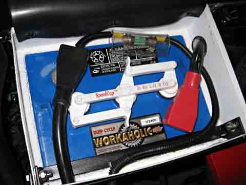
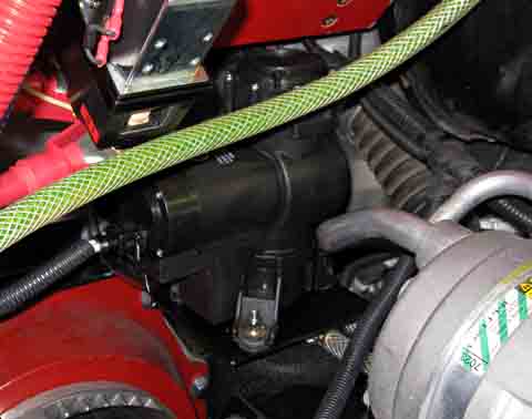
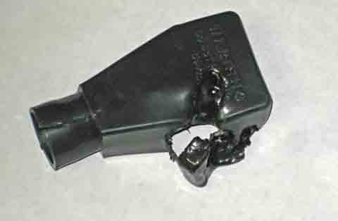
On December 28, on a fairly local drive, the truck just quit! I coasted over to the side of the road and parked. I tried to "start" it to no avail. On one try, after turning the key to the start position, I got the "click" of the controller driven contactor and figured that maybe something had overheated and that it was now OK. Wrong! I made it about 6 feet and it died again. I looked at the stock Chevy voltmeter for my 12 volt lighting battery, and the voltage was low. I figured that the voltage must have dropped somehow to a point that the controller would not turn on. It turned out that this was not the problem at all, but I was apparently blinded by the one bad item I saw. I had all the clues in front of me, but I did not adequately process them. Finally, after getting a ride home, which was about 3 miles away, I went back armed with a meter, battery, wires, etc. It only took a couple minutes with my meter to discover that I had an open in one of the rear battery packs. I lifted the bed and rolled back the neoprene on the two front boxes and immediately discovered a melted insulation boot. Under that boot was a melted battery terminal. I unbolted the cables from that battery. Of course, one of them was already pretty well unbolted. I bolted the two cables together to bypass the damaged battery and proceeded to drive home without any further problems. I don't know if there is any salvation for the damaged battery or not. The terminal is severely damaged, but I am sure the battery itself is fine. I may try casting the terminal back to a usable state. More research is needed. My first thought was to make an assembly of brass that clamped tightly to the portion of the terminal that is left and provided a bolt hole for the cable, but closer examination showed that the cross section at the bottom of the terminal is so small I am sure it would fail under high current. One thing I learned from this is that I will never again travel, even very locally, without a meter, small jumper cables, my schematics, and some basic tools. As it turned out, I did have my insulated battery wrenches with me, and I could have made the repair hours earlier if I had only read all the indicators correctly. I was just too focused on the low 12 volt battery! Ironically, I had just ordered additional meters from Ebay to monitor for exactly this sort of occurrence! I will have a digital volt meter monitoring the voltage of batteries 1 through 10, and another monitoring 11 through 20. If I see any significant difference between the two reading, something bad is starting to happen! If I see one at the proper voltage, and the other at 0, it has already happened! I also ordered one to accurately monitor the state of the 12 volt battery. As to why the terminal melted, I can only draw one conclusion: I failed to correctly tighten that terminal. I thought I inspected every terminal after initially completing the assembly, but I must have missed this one. One clue is that this terminal was one of the two that I left disconnected until I wanted to power up the whole battery pack. Oh, well! Onward and upward!
Terminal
Repair - Results: So So
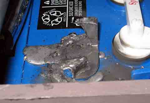
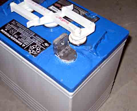
To make a long story short, I was able to make a mold and re-cast the terminal. In the process, I poured too much lead for the base and had to re-heat it to remove the excess. This overheated the top surface of the battery housing, causing it to delaminate.. After finishing the casting of the terminal, which came out fine, I used several repair materials in sequence to try to properly seal the battery top. The results look fine, and I continue to run the truck that way.
This is my progress
through January 2, 2009
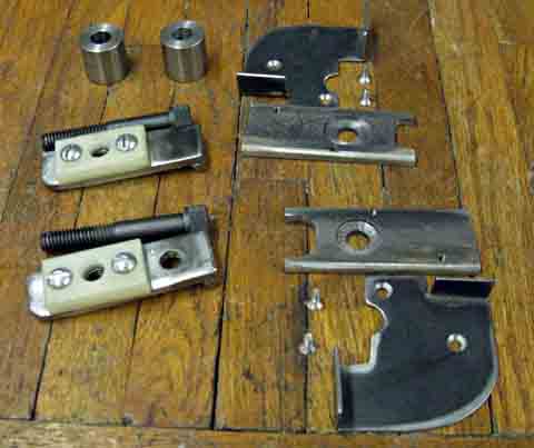
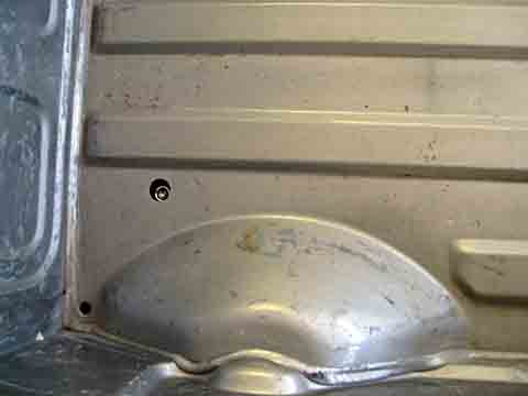
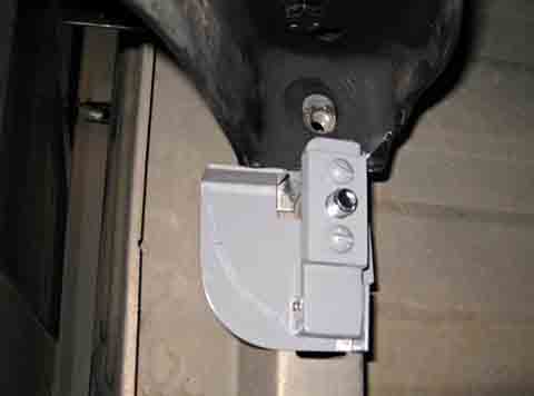
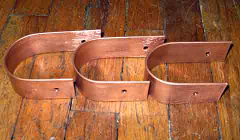
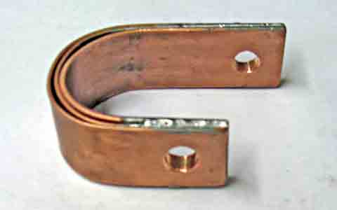
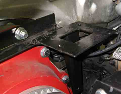
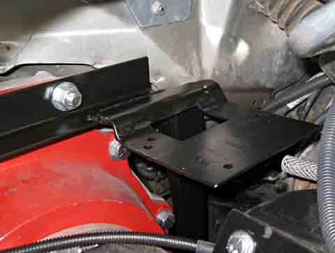
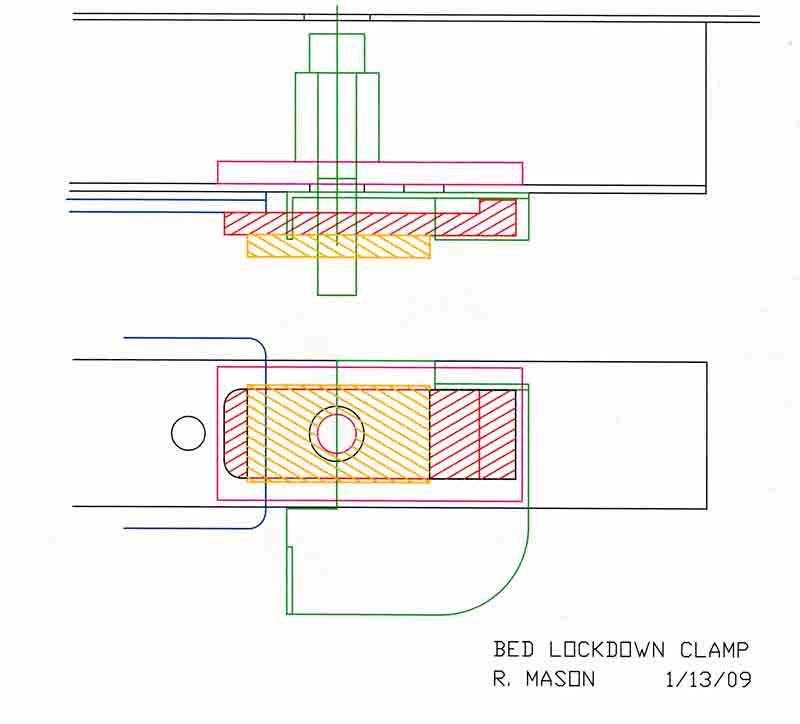
Follow-up to Battery Fix I installed the repaired battery in my truck this morning (1/3/09) and took it for a ride. Performance was normal. I took it to the bottom of a long upgrade and held the current at about 450 amps all the way up. I then opened the bed and felt the terminal I had repaired and it was no warmer than the others. This gives me confidence that I did not damage the internal connection to the battery plates in any way. I seem to be back up and and running at full voltage now! Further Follow Up 9/20/10 I raised the bed today in preparation for adding an additional 4 batteries, and found a lot of corrosion on the top of the repaired battery and on the battery hold down angle. I am obviously leaking acid fumes through the area where I repaired the battery. I have run this battery for almost 2 years after repairing it, so I don't feel too bad about replacing it now Bed Clamp Down The biggest annoyance I have been having since getting the truck running is the continual rattle of the bed as the truck drives over rough areas of the road. I finally got around to solving this problem by designing and building a pair of clamps which lock the front of the bed down to the frame. I looked into a wide variety of clamp down designs and finally settled on a fairly simple concept. I made a pair of swing arm clamps which rotate into position and clamp the bed down to the original bed mounting brackets.
After I completed
these
clamps, it was wonderful to drive the truck without the constant
rattle. It was really very quiet. The truck seems
to be
"tighter" now than it was when powered by the gasoline engine.
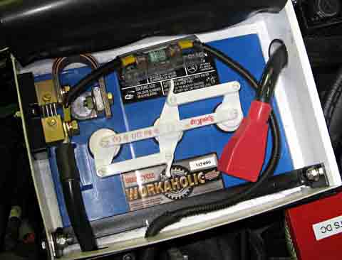
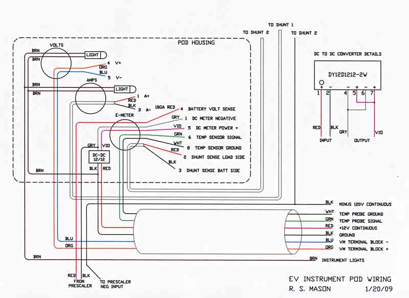
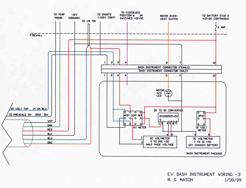
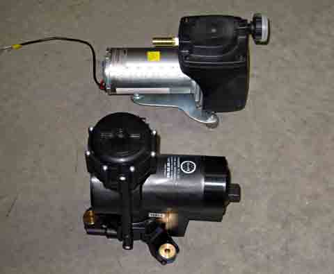
Additional Instrumentation I decided to enhance the instrumentation package by adding an E-meter, digital voltmeters which monitor each half of the battery bank, and a digital voltmeter to indicate the status of the 12 volt battery. The E-meter keeps track of all the current entering and leaving the battery pack and is in effect a fuel level meter. It also has many other functions to assist in monitoring the battery bank. The meters on the two halves of the battery pack are to make sure that there is no battery or connection going bad. If something does start to fail, it will affect the voltage on only the half of the pack where the failure is. By making sure that each half performs the same as the other, you are almost assured that things are OK. Shunt installation The first problem installing this additional equipment was installing another shunt in the main power circuit. The E-meter requires a current shunt which monitors all the current going into and out from the batteries. It must be the only thing attached to the negative terminal of the battery pack with all the connections made to the other end of the shunt. The only logical place to connect this is directly on the battery. The original cable going to the electronics board is easy to connect to the shunt instead of the battery. Connecting the battery terminal to the shunt is a problem. They are located so close that a standard cable cannot be fit in.
I decided to make a copper strap to do the connection, but have no good local source of copper bar. I decided to make my own from copper plumbing pipe. I took several lengths of 1/2 inch hard copper pipe and softened them by annealing. I now flattened them forming copper bars about 1/16 inch thick and 1 inch wide. To get the current capacity I wanted, I decided to stack three of these bars. This gives me a cross sectional area slightly greater than the 2/0 cable I have been using.
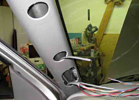
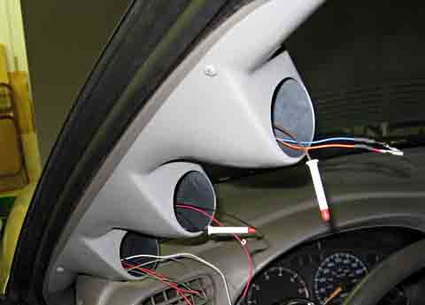
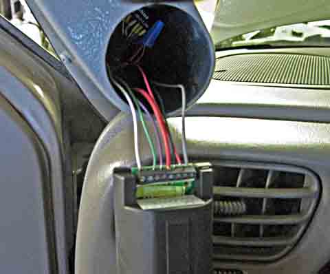
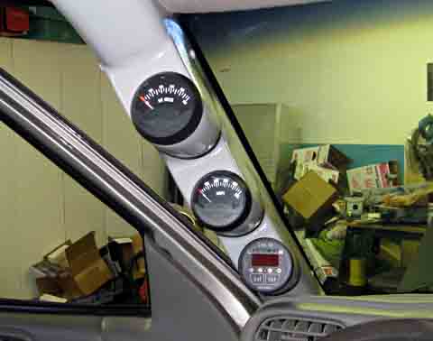
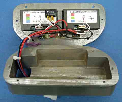
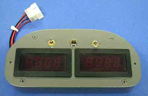
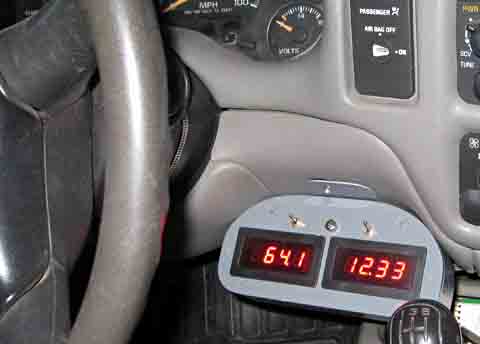
This is my progress through 1/16/09 Gauge Pod My temporary location for the voltmeter and the ammeter has not worked out too well. It is too low and is hidden by the steering wheel when in a normal driving position. (That is why it was temporary!) My plan is to now mount these two gauges and my new E-meter in a mounting pod on the left windshield post. This should make the meters much easier to see without taking my eyes off the road. I bought the pod from a specialty vendor who had a design for my specific truck model. There were many, many wires to run up through the existing windshield post. Most come from the center of the dash where the meters were temporarily mounted, but some come through the firewall from under the hood, and some from behind the driver's seat. I made access and clearance holes in the original post cover, which remains. The new pod mounts to the original post cover. I managed to get all the required wires into the clear space behind the post cover.
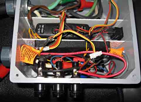
The standard E-meter is good for monitoring a maximum of 50 volts.. For EV use with much higher voltages, the company makes a prescaler to allow it to operate up to 500 volts. I decided to mount the prescaler in my charger meter box, as there is room for it, the electrical input connections I need are right there, and it gets it out of the way. I also mounted three fuseholders for the input to the prescaler and for the 60 volt tap I need for my digital meter pack. After completing the installation, I was reading on the Xantrex website where they warn you to connect the negitive input lead of the prescaler directly to the load end of the shunt. They caution that breaking this circuit while drawing significant current could destroy the Link 10 E-meter. As I have a fuse in that line, and where it is connected, unplugging the charger from the batteries would also open this circuit, I realized I could not leave it like it is. (I could not find any similar warning in the installation section of the manual they sent me!) I solved the problem by pulling the negative lead from its fuseholder, running a new wire from the meter box up through the cab, through the firewall and to the shunt. This wire now connects the prescaler the way they insist upon. In retrospect, I probably would have found a place for the prescaler either under the dash or in the engine compartment had I realized this limitation, but all the wires are now run and I will leave it. I then finished wiring the other parts of the system and checked everything out. It all works!
I have included wiring diagrams to show just how the various gauges are connected: I have also gone back to sections 6 and 7 and updated the High Voltage,the Low Voltage, and the Charger Meter Box Schematics to show the modifications needed for these added instruments. .
To go to the next section, click here |
||||||||||||||||||||||||||||||||||||||||||||||||||||||||||||||
|
Dick
Mason, Prescott, AZ 2/11/09
|
 .
.