Dick Mason's Electric Vehicle (EV) Conversion ProjectPart 3 Power Steering, Air Conditioning, and Front Battery Boxes 9/1/08 thru 9/20/08
Power Steering and Air Conditioning In the early planning stages of this conversion, I decided I wanted to keep my power steering and air conditioning. Many people doing conversions do not keep either. Both of these are a draw on the batteries, with the AC being a major draw. I don't care! It gets hot in Prescott in the summer and I want the ability to cool the truck. With such a small cab, I should be able to use it for relatively short periods. When it is off, there is almost no additional draw. The power steering load is minimal. After completing the rear battery boxes, I decided to concentrate on mounting the air conditioning compressor and the power steering pump. I plan to mount these in approximately the same positions they were on the IC engine. I considered welding a set of mounting brackets from angle iron, but decided that it would prove to be a nightmare to align everything properly. I ended up designing a flat plate mounted to the end of the motor and mounting the pumps at the upper end. Additional bracketry on the rear would provide the required stiffness and strength. I did a fairly complex layout on my CAD program, using
dimensions from
the original cast iron mounting bracket from the gasoline
engine.
To verify all the fits and clearances, I made a trial bracket from 3/8
plywood. It obviously was not particularly rigid, but allowed
me
to verify all the clearances. In the end, I found that
everything
cleared, but the hoses from the PS were very tight at the
bottom.
I also found that the pumps were higher than required. I
modified
my design to lower the pumps and move them sideways slightly.
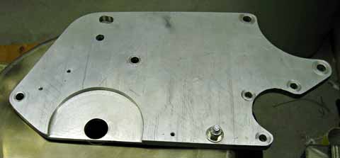
Aluminum Mounting Plate I used the modified design to build an aluminum plate. Fortunately I found a piece of aluminum that was just large enough, and used it. I band sawed the outer contours and used my original iron bracket as a drill jig for the pumps. After trial fitting, I decided I wanted the pulleys
closer to the mounting
plate. I made a spacer for the pump mounting area that mounts
on
the rear of the plate and spaces the pumps back 1/4 inch. I
did several
more test fittings, making additions each time I thought of something
else
that needed to mount on the plate. I have 3 tapped holes
around the
motor shaft to mount the speed sensor. After figuring out how
to
make the motor pulley, I found it would interfere with the main plate,
so I machined a 4 inch diameter area for added clearance.
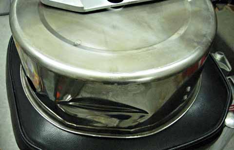
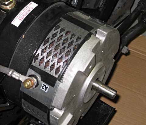
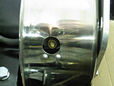
Rock and Water Shield When I received the motor, the manufacturer had included a sheet recommending that the brush end of the motor be protected two different ways. They suggested fastening window screen over the perforated metal band around the brushes, and even included a piece of screen. They also suggested placing a protective pan around the end of the motor to deflect debris and water away from the brushes, while still allowing air to circulate. I was very fortunate and found a perfect size pan at the Habitat for Humanity thrift shop for $5. It was 12 inches in diameter and was made of stainless steel. The height was perfect. I punched a shaft clearance hole in the center of the bottom, and holes that matched the mounting pattern of the motor. The pan is sandwiched between the motor and the aluminum
mounting plate.
In talking with my good friend, Keith Scholl, I was
describing how I
had to disassemble a number of things to change the cables that attach
under the pan. He shamed me by saying I was just like all the
other
automotive engineers, that built things that cannot be worked
on.
That got me to thinking how I could improve things, and I decided to
punch
holes over the two terminals. This allows me to change and/or
tighten
the cables without disassembling anything. Thanks, Keith!
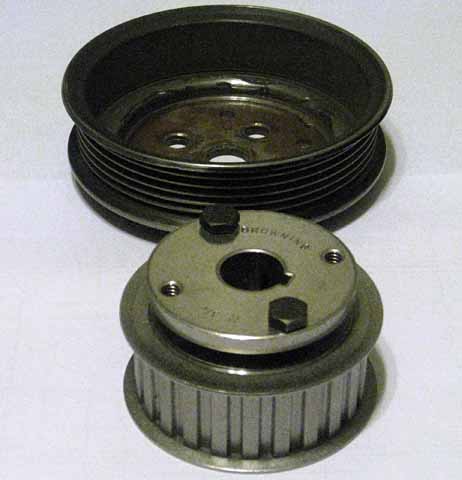
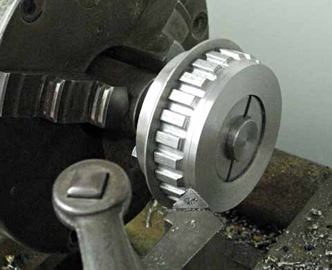
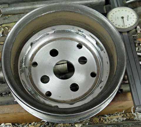
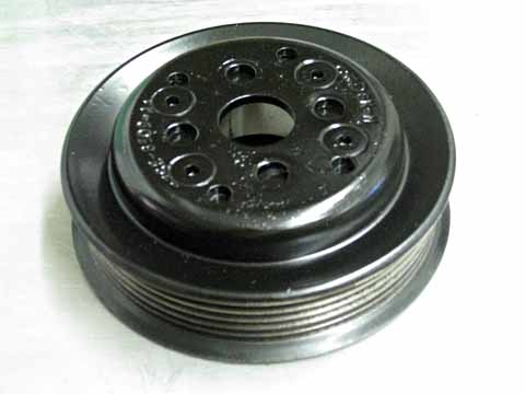
Drive Pulley The next project was to make a pulley for the motor shaft to drive the pumps using a serpentine belt. One of the other S-10 converters, whose information I read suggested a pulley from a 96 Saturn. I went to a semi-local wrecking yard. I immediately went to the area where the Saturns were and found that they all had 5 rib belts. Mine is a 6 rib belt. Chevy must have changed to a wider belt on the later models. I looked at many, many cars and the closest match I could find was on a Ford Mustang. It had a two tier pulley with the smaller one being the size I wanted, and they were 6 ribs. I removed the pulleys from the car, expecting to find two nested pulleys. Unfortunately it was a single assembly. I cut the two pulleys apart and removed some excess metal from the inside of the small pulley. Now that I know how it is made, I would do it somewhat differently if I did it again, but this came out fine. After cutting out some excess metal, one section was very thin, so I placed a bead of weld around the inside edge to thicken it. I felt that this pulley would now do just fine. I located and bought a lug belt pulley from Grainger
online. I
bought a diameter I thought would require a minimum of machining, and
selected
a wide one figuring I could cut it down to the exact thickness I
wanted.
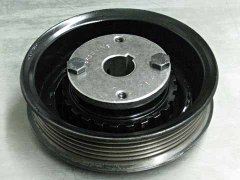
It uses a split taper bushing for a very secure attachment to the
shaft.
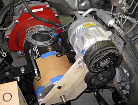
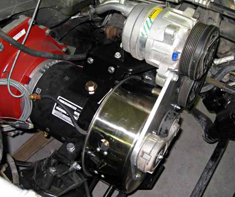
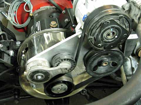
Once I finished the pulley, I could assemble all the
pieces for the
final (I hope!) time. I mounted the pan, the mounting plate,
the
AC and PS pumps, the belt tensioner, the motor pulley, and the rear
mounting
bracket for the pumps. This bracket ties the factory brackets
securely
to the motor body.
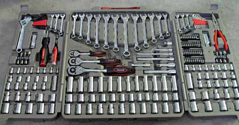
More Tools! In the course of working on the truck, I needed to remove a couple of the rear bumper bolts. I could not do it! It was an 18mm bolt head and nut. I had no 18mm wrench of any kind, none of my SAE sockets would fit, and I couldn't even get an adjustable wrench on either end, as both sides were nested in channels. My solution was to buy a very complete set of wrenches from Costco. The set includes socket sets in 1/4, 3/8, and 1/2 inch drive sizes, deep well sockets, and complete sets of combination wrenches, and allen wrenches,all in both metric and SAE sizes. There are also screwdrivers with many bits, pliers, and an adjustable wrench. All of this is in a folding plastic case which allows me to easily take a very complete tool set where ever I need it. Of course it also includes several 18mm wrenches for my bumper bolts. The deep well metric sockets have been wonderful to have
during all
the installing and removing (multiple times) of the power steering pump
and the air conditioning compressor.
This is my progress through September 12, 2008 Under-hood Battery Boxes My next project was to design and build the two front battery boxes. The boxes under the bed can accommodate 18 batteries, which leaves 2 more batteries to house. Most converters place 4 to 6 batteries under the hood, and typically place them across the front, just behind where the radiator used to be. As I am keeping the air conditioning, I did not want to block the airflow through the condenser, which is the same size as the radiator, and just in front of where it was. I decided to place one battery on each side of the
condenser, overlapping
it somewhat, but leaving a large gap between for airflow. A
battery
would fit in very easily on the passenger side, but not so easily on
the
driver side. I tried several layouts there, and all would
interfere
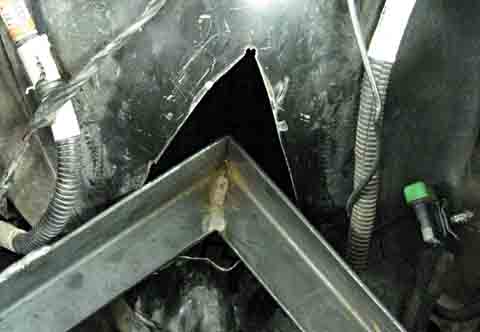
with something. I finally took some measurements and decided
to let
the corner protrude through the fender panel. My measurements
showed
that the tire would easily clear it in all situations except a hard
right
turn with the spring fully compressed. There it would be
almost in
contact. I cut a triangular opening which allowed the box
corner
to extend past the fender line by a couple of inches. I
bought a
stamped steel fence post cap which I plan to cut to shape and weld on
the
tire side of the fender to seal the opening. This cover has a
flat
surface that will allow the tire to harmlessly rub if it should ever
come
in contact. If I left the corner of the box without
protection, any
tire contact would be to a sharp point and possibly damage the tire.
I Initially mounted the box bases to the truck frame
members with brackets
on the bottom, a tie to the sheet metal along side the radiator, and
straps
from the radiator top rail down to the box. I didn't like the
result
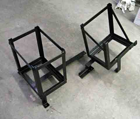
of this, and decided to modify the boxes to be a single assembly that
mounted
only to the frame. I removed the hanging straps, added an
additional
bracket to the frame on one side, then added a strong member between
the
two boxes to make them into a single assembly. I made this
connecting
member in two parts that bolt together during installation.
This
made it possible to install the two boxes.
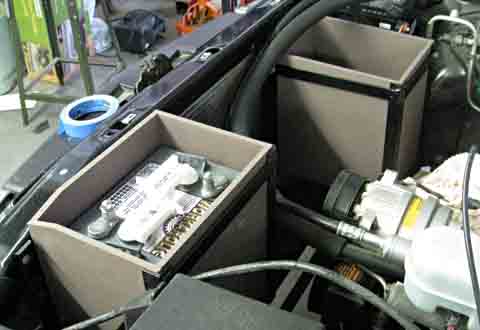
I then built the boxes up with corner angles and top braces to securely hold the batteries and the wooden panels around them. After completing the installation, I discovered an
additional problem:
I could not install a battery in the passenger side box! The
air
conditioning hoses pass over the front of the box. I had
always assumed
these were flexible enough to clear the battery during installation,
but
they just would not get out of the way without crimping them rather
badly.
To solve this problem, I cut a corner angle and its two top braces
loose
from the rest of the box and made the changes needed to bolt them back
to the box. Now I can remove 3 bolts and the corner of the
box removes,
making it easy to install a battery without touching the AC hoses.
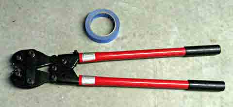
Heavy Duty Cabling My welding cable, which had been back-ordered, finally
arrived, along
with the cable crimpers. I wanted to see just how much of a
chore
it was going to be to make the 30 or so cables I will need, so I
started
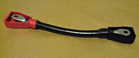
with one I can use right now. The motor needs a connection
between
one of the armature terminals and one of the field ones. This
needs
a cable 10 1/2 inches between terminal holes. I used the
stripping
tool I just bought and cut the insulation at one end of the
cable.
Then with much effort, I managed to remove it from the cable.
I slightly
under-cut the depth so as to not nick any of the cable
strands. I
then need to bend the end in several directions to pull the remaining
thin
section of plastic apart.
The crimper is straight forward in operation, although somewhat awkward due to its size. After completing the first end, I cut the cable and stripped and crimped the other end. Now I cut a piece of shrink sleeving for each end and shrunk them in place. This sleeving has an adhesive layer on the inside, so in addition to conforming closely with the cable and lug, it is actually sealed to them. The hardest part of the operation was putting the insulating boots on over the lugs and shrink sleeve. I had determined that I do not need to put them on the cable before crimping, but that they will fit over the lug. Using a little soapy water, I found I could work them into place with effort. The boots really have to stretch to fit over the sleeving. The finished cable came out fine, and took about 30
minutes to complete.
I suspect that future cables will go faster.
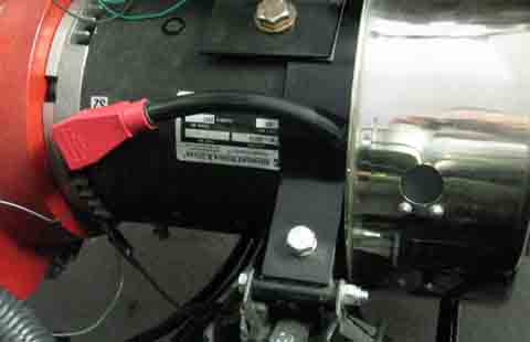
I then installed the cable on the motor. It
was a little awkward,
but very doable to make the connection under the pan. I
pulled the
boot to the side and hooked the lug on the terminal. It was
then
quite easy to place the washer and the nut on the terminal working
through
the hole and reaching under the edge of the pan. I tightened
the
nut using a socket wrench, then worked the boot back into position.
I have started the design for my next project, the mounting board for the control electronics. This will be a horizontal board under the hood, which mounts the controller, the DC to DC converter, the contactors, the fuses, etc. This is my progress through 9/20/08 To go to the next section, click here. |
||||||||||||||||||||||||||||||||||||||||
|
Dick
Mason, Prescott, AZ 9/21/08
|