Dick Mason's Electric Vehicle (EV) Conversion ProjectPart 2 Installation of the motor and adapter through completion of under-bed battery boxes. 7/18/08 thru 8/31/08
Do I use the Clutch? July 18, 2008
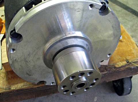
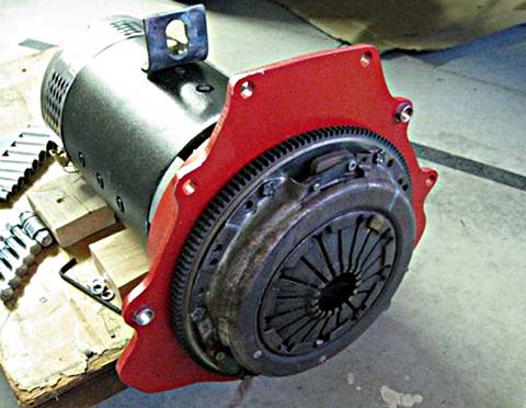
The proponents of the clutch system say that using no clutch will put an excessive strain on the transmission, and that the clutch provides added utility and safety as an additional way to disconnect the motor from the drive train. I decided to use a clutch system for two reasons: First, I feel more comfortable having a clutch, as I have no experience yet with an electric vehicle. I know the clutch system will work for me - a clutchless system would be an unknown. Second, if I change my mind and decide to go to a direct connect system, it is easy to modify what I have to eliminate the flywheel and clutch pressure plate. In place of the flywheel I would make an aluminum plate to which I would bolt the existing clutch plate. The transmission shaft would fit into the splines normally and I would have a direct drive, clutchless system. If I started with a clutchless system, there would be no way of adding a clutch. For the time being, at least, I will have a clutch. Assembling the Motor, Adapter, and
Transmission
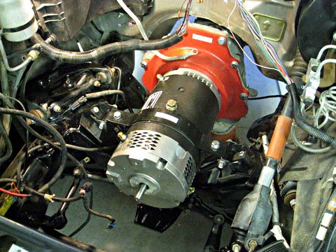
Do I need the Engine Computer? One of the concerns I have had is whether or not I need to keep the original engine computer. I went through all the signals going into and out of the computer and decided the only ones performing functions I still need are the VSS (Vehicle Speed Sensor), which drives the speedometer, and the air conditioning controls. I should be easily able to bypass the computer for the A/C, but I know nothing of the VSS. Once I had the motor installed, and the back of the truck up on stands, I could run the motor, driving the rear wheels. Of course I only drove it with 12 volts, but that was enough to get me to about 8 miles per hour in first gear. As I was already overloading the 12 v. power supply, I decided not to try any higher gears. A rough measurement showed the motor pulled about 100 amps initially, dropping to about 50 amps after getting to speed. My power supply is good to about 40 amps, but seems to take the overload quite well for short periods. Back to the VSS and the speedometer. I
attached pigtail test leads
to the VSS signal from the transmission sensor into the computer, and
to
the lines that drive the speedometer head. I was hoping that
the
computer only changed the wave shape, but not the frequency.
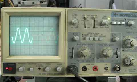
I set up my oscilloscope and first looked at the raw signal from the sensor to the computer. It was a sine wave of about 15 v peak to peak, at about 294 HZ (at about 8 mph). I then reconnected the scope to the output of the computer and saw a square wave, from 0 to 12 v at about 10.6 HZ. So much for being the same frequency! There is about a 27/1 ratio from input to output. I'll keep the computer for the time being. 8/6/08
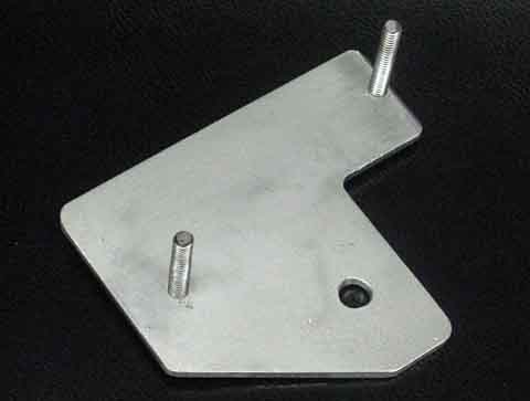
Throttle Assembly Mounting I decided to install the new throttle assembly next. This is a dual Hall effect electronic throttle which interfaces with the speed controller I have on order. I had no idea how much of a problem it would be to mount it properly with the pedal in the correct position. It turned out to not be bad at all. The original throttle was on a bracket mounted on three studs protruding through the firewall. It turned out they were welded to a plate which was on the engine (now motor) side of the firewall with the studs extending through. Positioning the new throttle, it appeared that one of the studs lined up exactly to keep the throttle in the same place as the original. The new unit mounted on only two studs or bolts. I removed all the original parts, fabricated a new
doubler plate with
two pieces of threaded rod threaded into tapped holes and locked with
nuts
on the back side. I drilled a new hole in line with the 2nd
mounting
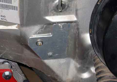
hole and put the new doubler studs through the firewall. I
mounted
the new throttle on these studs. I also bolted the backing
plate
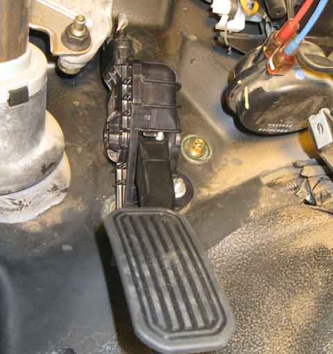
to the firewall using one of the now unused holes. Placing a
rubber
grommet in the hole where the throttle cable originally went through
the
firewall and feeding the electric cable through this hole, and plugging
the connector into the new throttle completed this installation.
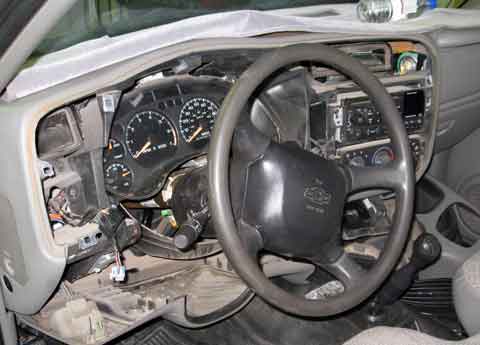
Initial Look at Instrumentation I decided that since I now have the voltmeter and
ammeter, I should
look at how to mount these in the original display panel. I
started
pulling panel after panel loose, and finally got to where I could
remove
the gage assembly. I will eventually mount my gages here in
place
of the fuel, oil pressure, and temperature gages. The 12 volt
meter
should still be useful. I will also have to disconnect
several of
the indicator lights from the logic network in the gage display and run
them out on separate wires. That will come later when I have
a delay
in other areas.
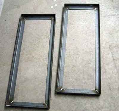
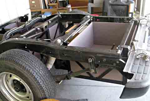
Determining the Battery Configuration At this point I still do not know what battery configuration I will be using. It's time to fix that! I contacted my motor supplier with 4 possible battery configurations. They offer a service to run your data through a program which predicts the performance of the finished vehicle. By comparing my different possibilities, I can see just what the pros and cons of each configuration and then balance that with the final cost. The possibilities I am considering are 2 120 volt systems using twenty 6 volt batteries of different capacities, and two 144 volt systems. One of these uses 18 8 volt batteries and the other uses 24 smaller 6 volt batteries. After carefully reviewing the results of these calculations, I eliminated the two 144 volt systems. The 18 8 volt batteries just had too little capacity for use in hilly Prescott, and the 24 battery system would be a nightmare trying to place all the batteries. Battery Boxes I have tentatively selected the 120 volt system using the largest (and most expensive) batteries, but it has the best performance of the 4 systems. Using either this system, or the one with lower capacity batteries makes no difference in the battery boxes, as the two batteries are the same size except for about 1/4 inch of height difference. My plan shows two 4 battery boxes in front of the rear axle, and a 10 battery box behind the axle. There will also be 2 batteries under the hood. Now it's time to start getting my hands dirty and build some battery boxes! I have done detailed layouts of my battery boxes and now know exactly what size and shape to build. The boxes will be frames of 1 1/2 inch angle steel. These will be lined with plywood on the bottoms and the sides. I will use thin spacers between the batteries at the base to keep them about 1/4 inch apart. This allows for the normal swelling of the battery sides and prevents them from becoming so tight they cannot be removed and replaced. I am now about two months into this project (about 1 month since I started pulling parts from the car). I cut all the angle pieces for the bases of the two
"front of the axle"
battery boxes and welded them together using my new MIG
welder. Boy
is it easier to get a decent weld with this machine! I am not
saying
that my welds are particularly pretty, but they sure are much better
than
I ever was able to do using my "stick" arc welder.
I still
have the problem of not always being able to see where I am welding as
my bead continues. Some of my welds wander off to the side
and have
to be redone in the correct location. All in all, I am very
happy
how it is going.
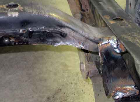
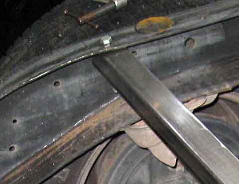
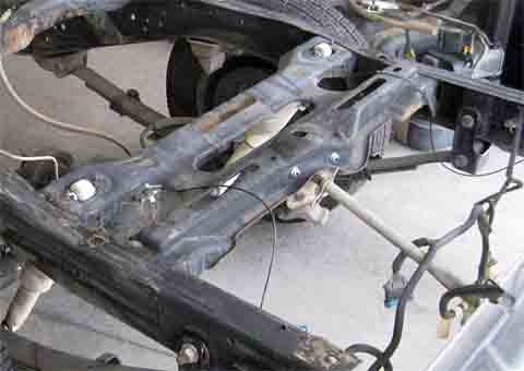
Frame Clearance One problem I encountered was trying to avoid
interference with the
bottom of a cross member over the batteries. The bottom
curved downward
quite a ways from the frame, and would have required the battery boxes
to be located lower than I wanted, or so far toward the center of the
truck
that other interferences occurred. My solution was to modify
the cross
member. I torch cut a fairly large bottom section of the
cross member
and welded on a reinforcing plate. The net result was much
more headroom
extending within a couple inches of the frame.
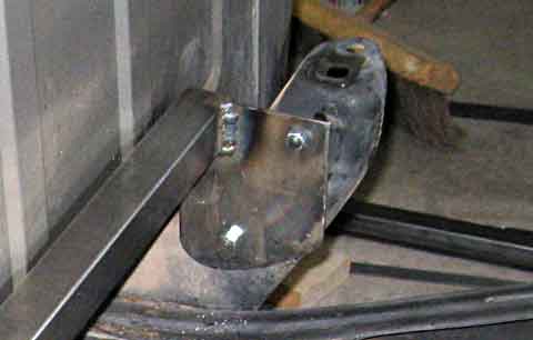
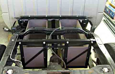
Front Battery Box Supports I used 1 1/2 square tubing to support the battery
boxes. I have
one piece going across the frame at the front of the battery boxes and
another at the rear. The front one is welded to a pair of
brackets
which then bolt to two of the bed supporting brackets. The
rear rail
merely bolts through the top web of the frame. Where ever I
bolt
through the square tubing I either weld a pipe into the tubing which
the
bolt passes through, or I use a 1/4 inch doubler the full width of the
tubing. Each of these methods ensures that the bolt will not
collapse
the tubing.
Beefing up Box Supports 8/22/08
I decided to add a 1/8 thick strip, welded to the top and bottom of the front cross member. This will increase the safety factor to over 10 to 1. This is the best method for beefing up this member as the bolts holding the battery box run through the square tubing vertically, limiting what I can do above or below the bar.. For the other cross members the racks bolt through horizontally. This allows me to weld a spacer to the bottom center of the tubing, then run a strip along the length, welded to one end, passing over the spacer, and then on to the other end. This will add significantly to the stiffness and the load carrying capacity of the beam. A very simplistic, conservative check shows a yield safety factor of over 14 to 1. I stiffened the battery boxes considerably by welding diagonal strips on both ends, and along the length from the center up to each end hangar. This has always been in my plans, and keeps the stress to about 1/18 th of the yield stress. It looks precarious to mount the front rack rear cross
members with
only one 3/8 bolt at each end, but the stress here is only about 1/89
th
of the yield.
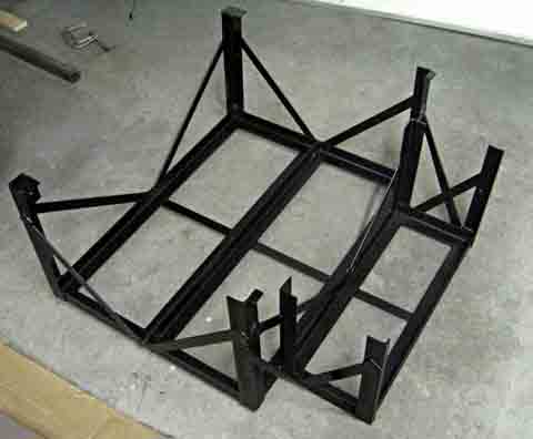
The cross member mounts for the rear battery boxes will not require any stiffening, as the front will be what is left of the factory cross member, and is easily strong enough. The rear mounts to another 1 1/2 inch square tube. The stresses are much lower in this member, as all the weight is hung from an area very near the supported end. No stiffening will be added to this member. After completing the supporting cross members for the
front boxes, I
completed the box frames by adding angles in the corners to use in
hanging
the boxes, as well as diagonal stiffeners and hangars to support the
middle
of the longer pieces.
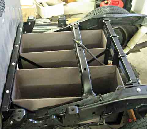
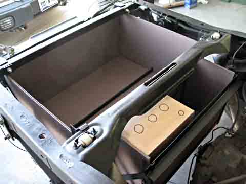
Lining the Battery Boxes I then cut 3/8 plywood to fit the bottom and sides of
the boxes.
After painting these, I installed them. This completed the
front
battery boxes and I installed them in the truck.
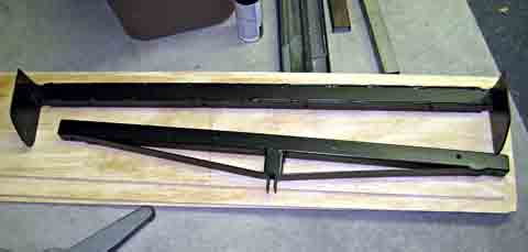
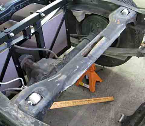
Cross member Modifications I then started looking in detail at the rear battery box. This will hold a total of 10 batteries behind the rear axle. The rear factory cross member is a massive thing. The front half mounts the upper end of the rear shock absorbers and has brackets to prevent twisting of the frame rails. The rear half primarily mounts the cable mechanism that holds the spare tire up tight under this cross member. I decided to remove the rear half in the interest of providing much easier access to the batteries. I torch cut the rear half out and finished the cut areas
with my angle
grinder. There was a flange on the rear side which presented
a potential
interference when changing batteries. I heated this area with
a torch
and hammered it straight down. The location of the rear side
of the
remaining cross member is located within 1/8 inch of the front of the
main
portion of the rear battery box. This is ideal for mounting
the box.
I added a rear cross member at the extreme rear end of the frame rails
to support the back end of the box. This member will also
support
the hinges that will allow the bed to be raised somewhat like a dump
truck,
to allow battery access..
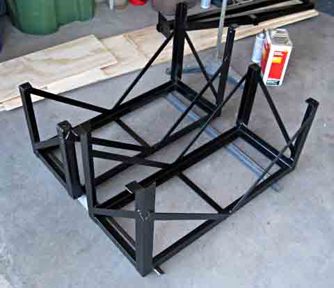
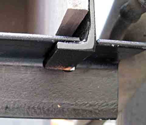
Rear Battery Box I then concentrated on building the rear battery box. It is also a weldment made mostly from 1 1/2 inch angle steel. I reinforced it using 1 inch bar stock. There were several challenges in mounting so that I could still install or remove batteries. The rear 4 batteries extend slightly under the rear cross member. This means I need clear vertical access to the front batteries. I can install the rear ones first by sliding them back under the cross member and letting them settle into the rack. The front batteries then simply drop into place. The small 2 battery rack in the front was a little more
difficult.
These batteries rest about 1/3 of the way under the factory cross
member.
To change these batteries, I needed to make the front of the box easily
removable as well as providing structural strength for
safety. I
solved this problem by cutting the corner rails so the space between
them
was at least as wide as the two batteries. I then made it so
the
wood panel would drop into slots and rest in the correct
place. To
the top of this panel I fastened an angle which drops over the corner
rails.
The end result is a panel which simply drops into place, with a top
structure
that is very strong for loads toward the front.
It looks very intimidating having so many batteries
located so far to
the rear. I did a center-of-gravity check, and weight of the
full
compliment of batteries will be centered about 1 foot ahead of the rear
axle. This is just about where the truck was designed to
carry its
payload.
This is the progress through the end of August 2008
To go to the next section, click here.
|
||||||||||||||||||||||||||||||||||||||||||||||||
|
Dick
Mason, Prescott, AZ 6/21/08
|