Dick Mason's Electric Vehicle (EV) Conversion ProjectPart 10 Additional Tasks done 6 Months or More after "Completion" 7/1/09 thru Present
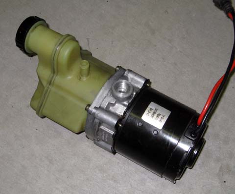
I have been successfully driving my truck around Prescott for most of my local errands, with no further problems (after the battery disaster I described in the last section). I now have almost 1000 miles on it as an electric. This is almost as much during the same time as I have put on my Subaru, which I use for longer drives. There are still several things which I need to do. Electric Power Steering The first thing I will do is to change my power steering over to an electric pump rather than the stock mechanical one which the drive motor is now powering. There are a couple of problems with the existing pump: First, of course it only works when the motor is running, so when I am trying to maneuver into a parking spot, I have no power steering. Second, reports on the Internet say the power steering pump uses as much as 20 HP from the drive engine (or motor). As I need all the power I can get to propel the truck, I am happy to remove this load. It is true that the main battery pack ends up powering it either way, but this way the drive motor has more power to move the car, and I believe the electric pump is more efficient. I bought a pump from a Renault truck (which is not available in the United States) from a fellow in Isreal, who sells quite a few of them on Ebay for electric conversions like mine. He also sells to owners of performance cars where they do not want the additional drag of the pump (up to 20 HP they say!) to be taken from the useful output of their engines. This pump automatically senses the steering load and idles at about 150 psi, increasing to up to about 1500 psi when the demand is there. This results in about a 5 amp draw at idle, and about 50amps during hard use. This is all from the 12 volt accessory battery. These figures equate to less than one horsepower in the high power mode. I can only assume the high draw of the original pump is because the pump has to be designed to deliver adequate pressure and flow at idle, but also operate at the maximum rpm of the engine, where the power draw would be much higher. My
first problem was to determine what type of fittings I need to connect
the new pump. The original one uses a proprietary fitting
only
found on some power steering systems, but not on my new pump.
After a lot of measuring and fussing around, I finally
determined
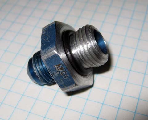
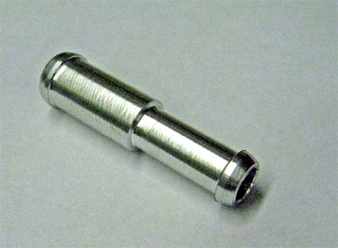
that the pressure fitting on the new pump is a metric one, 16 mm in
diameter with a 1.5 mm pitch. It is a straight thread and
needs
an o-ring to seal it. The return line is a 12 mm barbed
fitting
which uses a plain hose and hose clamp.
I
researched metric fittings on the Internet and found a few listings for
a n M16 x 1.5 adapter to a standard JIC type fitting. I
didn't
want to take the time to order this from the East coast, so checked my
other options first.
I went to NAPA to see what they could do. They make hydraulic hoses, but do not make normal power steering hoses as the ends are very specialized. They could make me a hose with a JIC fitting (the commercial equivalent of the military AN fittings) on one end, and a 3/8 diameter crimp fitting on the other end. My original pressure hose was rubber with 3/8 steel tubing crimped into the ends. This tubing had the special ends to fit the steering pump and gear. By cutting off the fitting from one end of my existing hose and crimping it into the new hose, I would have my high pressure connection - almost. I would still need the adapter from the metric pump thread to a JIC or AN fitting. NAPA lists the adapter as a special order part. A quick search by the salesman found the only one in the country at a NAPA store in Ohio. I passed. Digging through my junk box, I found a surplus AN fitting with an AN-6 (9/16 dia) on one end, and an AN-8 (3/4 dia.) on the other end. The large end of this fitting had plenty of material to machine to the metric size, while the small end fit the new hose.. Problem! My lathe is only set up to cut American style threads (16 tpi -threads per inch, 18 tpi, etc.) The 1.5 mm pitch is equivalent to just under 17 tpi. I did discover that one of the power feed speeds resulted in just about 17 tpi, so I tried that. The power feed is not a precision feed and there is no way to make multiple passes (as you must to cut threads) and align the thread precisely again. I set up the lathe for this feed, engaged the feed clutch and made about 10 passes never disengaging the feed. At the end of each pass, I would turn off the lathe, pull the tool back, reverse the lathe to move it back to the right, feed the tool back in and repeat. This worked just fine, and I ended up with a smooth, snug fitting thread. I cut a relief in the flange for an O-ring and the job was done!
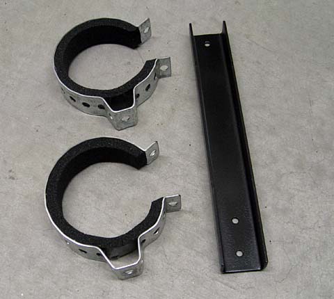
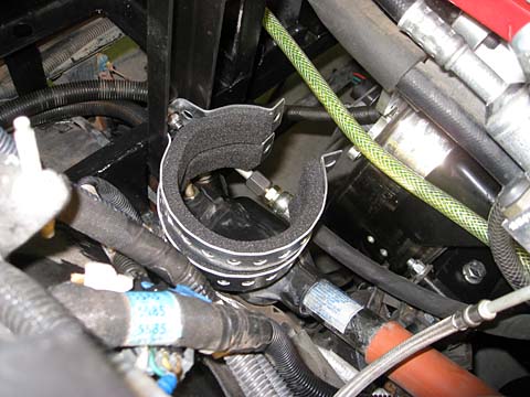
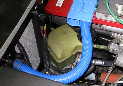
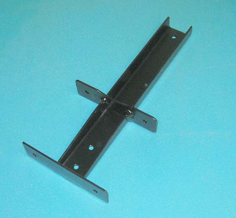
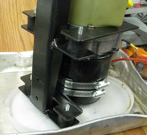
I
chose a piece of 2 x 1 x 1/8 channel to mount the pump to the rear side
of the left battery box. To do this, I bolted the channel to
the
battery box and attached a pair of formed loops made of perforated
steel near the bottom of the channel. I lined the loops with
foam
weatherstrip material and snuggly clamped the motor into these two
loops. This provided a stable, noise and vibration isolated
mounting for the pump.
The
metric adapter and the new pressure hose I bought connected the
pressure side of the pump line. The low pressure side now had
a
slight problem: The hose off the old pump was 3/8 inch inside
diameter, and the hose to fit the new pump was just shy of 1/2.
I
had already bought a length of hose to fit the new pump, but had no way
to connect the two hoses.
I machined a barbed fitting with a 3/8 diameter on one end and 1/2 on the other. Now I can connect the two hoses together and finish the connection to the pump. This worked out well, as the original hose was too short to reach the new fitting.
I
made a temporary electrical connection to the pump. It seems
to
work just fine. At idle it is fairly quiet with the motor and
pump running at a relatively slow speed and drawing about 6 amps from
the 12 volt battery. When I turn the wheel and put a load on
the
hydraulics, the pump "works harder", but doesn't really seem to run
much
faster, with the current rising to about 20 amps. I think
some of
this current was limited by my lightweight jumper clips. I
expect
it will pull more under load when I finish my wiring.
Even with the artificially low current, it seemed to allow me to turn the wheels easily when stopped. That is the worst case. I then went ahead and finished the wiring. I installed a relay on the top of the mounting bracket and connected it to a fused high current connection on the main fuse panel.
Update
of 5/22/10
The pump has been working quite well, but recently it has become noisy! It sounds like there is something loose inside the pump causing an erratic clicking and rattling sound. There may be truly something wrong inside the pump, or it may be poor mounting allowing the pump to contact parts of the truck. It is really hard to tell. There is very little clearance around the pump, and my very soft isolating foam also allows quite a lot of pump movement. To solve this problem once and for all, I decided to remove the pump and disassemble it to verify the condition of all the internal paarts. When I replace it I plan to use a different, more constrictive mounting system.
Update
of 12/20/2010
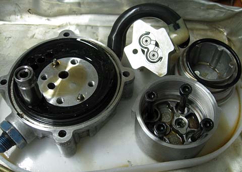
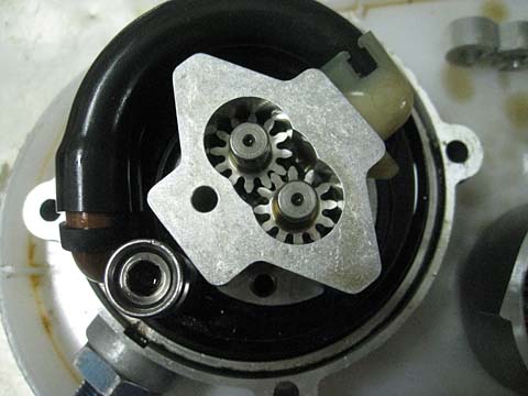
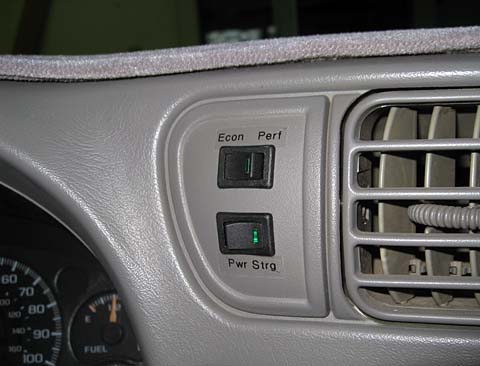
My steering pump quit completely. It will occasionally run for a short period and then quit again. I checked my connections and verified that I have power to the pump motor whether it is working or not. I pulled the pump from the truck and checked it out on the bench. I can get the motor to run by moving the power wires just right. When I let go of the wires, the motor quits. I decided to open the motor even though it is staked together and is not servicable. Using a cold chisel I carefully tapped the staked tabs to loosen their bite and finally just tapped on the end plate and sucessfully removed it. It was very dirty inside the motor. It looked like a combination of grease and carbon dust. After initial cleaning I inspected it and found the brushes were totally worn out. This was a very high mileage used pump! I attempted to contact the original seller, but did not receive a reply. I ended up buying a brand new factory pump from a supply house in Great Brittain for somewhat less than I had originally paid for the used pump. This pump was identical to mine and installed without any problems. It is quiet and works great! I just received a reply from the original seller, who apollogized for his delay, saying he just got out of the hospital after surgery. I have asked him what a working motor will cost. If I get this, I will have a complete working spare. Switches I mounted two switches on a blank dash panel. The top switch will be used to select one of two different sets of data within the controller. I will have an economy mode which limits my driving current to 350 amps, and a performance mode which will allow up to 500 amps. The bottom switch is used for this project and allows the power steering pump to be turned off. The pump will only run when the ignition is on, this switch will allow me to turn it off when the ignition is on.
My first drive
through the
city was very successful. It was a pleasure to be able to
easily
turn the wheel even while standing still. On the road, the
steering was a little firmer than before, but it was well within my
comfort zone.
Parking in the parking lots was a pure joy! I
found that the truck handles very well on the road with the pump turned
off. A normal corner is a little tight, but easily done
without
the pump. Of course with the pump on, all turns are very easy.
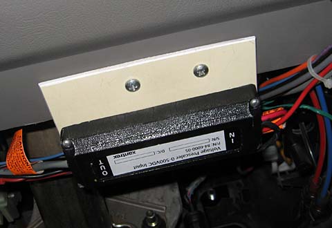
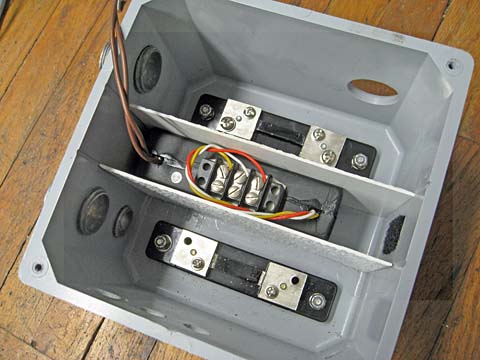
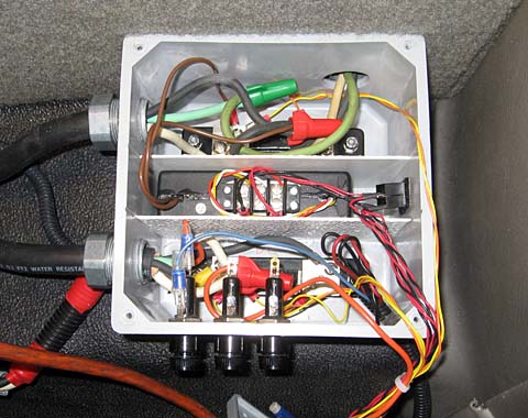
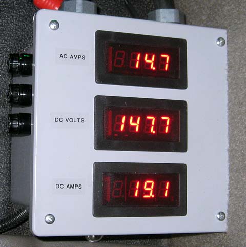
It may just be wishful thinking, but I swear the truck now has better performance! 8/8/09 I connected the MODE switch to the controller and connected my laptop to change the program. I set the Economy mode to a max of 350 amps and the Performance mode to a max of 500 amps. This is 50 amps higher than the single program I have been using to date. I have found that it is very difficult to limit my amperage when climbing a grade. The Economy mode should help. I took it for a test drive and all is well. 350 amps is fine for normal driving. I don't start out quite as fast, but still keep up with most other cars. If I need a burst that is beyond the 350 amps, I flick the switch and can feel the immediate boost in performance. As I reported earlier, I built a meter box to monitor my battery charging. This box included an AC ammeter, a DC voltmeter, and a DC ammeter. At a later date, I included the prescaler for my E-meter, noting from the schematics that I had most of my needed connections already in that box. After carefully reading exactly how the manufacturer wanted the wiring done, I discovered that I really had only one wire and had to run all the rest from the dash area to the box. The prescaler is used to allow the meter which is usually used with a 12 volt system to work with up to a 500 volt system. Recently a minor disaster happened. I am not sure just what happened, but one meter did not light up and another remained lit, but blank. I don't know if a nearby lightning strike, or a power line surge, or what other occurance took them out, but something did. I later found out that one DC to DC converter and two meters were all bad. I decided it was time to re-build this box. The first thing I did was to order new meters and DC to DC converters. This time I ordered LED meters as opposed to my original LCD ones. They may be more tolerant (or less) but they are different. I then removed the prescaler from the box and mounted it under the dashboard like I should have in the first place. The wiring runs are much cleaner now. I was able to connect to the same electrical signal that I had in the meter box under the dash, so no wires are needed to the back now for this circuit. This change was allowed by the very specific manufacturer's instructions describing the exact connection point they wanted for each wire. When I charge the batteries at home, I plug into a 230 volt outlet. Away from home, I can plug into any 115 volt source. The power supply I use must provide full output in either case. I had originally used two power supplies in series to get my 12 volrts DC. These have worked well, but I have since found a supply with both +12 and +5 volt outputs with a 100 to 240 volt input range that I will use. This supply is rated at 2 amps output on each voltage, so will have plenty of capacity to power a vent fan for the batteries I mount in the toolbox. This fan will only be needed during charging, so this supply will work fine. Another small change I made was to use PVC solvent cement to glue thin PVC spacers to one end of each meter cutout. The size I made the cutouts left the meters loose enough that they could easily be bumped out of their mounting. These shims corrected that after I machined them to the exact size I want.
September
25, 2009 It took about two weeks for the meters to arrive
from
China. Once they did, it took only a few hours to finish
wiring
the meter box and to install it in the truck. Of course since
it
had already been installed there, everything lined up and installation
was fairly easy.
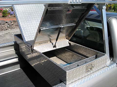
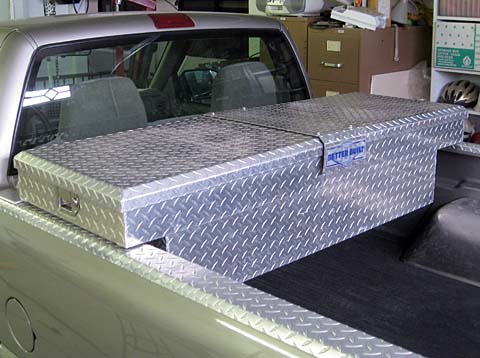
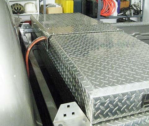
I have been somewhat disappointed with the range of my truck. All my initial calculations, both my own and those of experienced vendors indicated I should get a 40 mile range using an 80% discharge of the batteries. In reality, I have not gotten much over 25. I think it would meet my expectations fairly closely if I lived in a flat, level area. Unfortunately Prescott is very hilly. I seem to be always driving up hill or down hill, never level. In an attempt to overcome the problem of the hills, I have decided to add 4 batteries to my system, changing from a 120 volt system to a 144 volt system. A major obstacle is where to put the batteries. I have looked at re-packaging all my equipment under the hood, but cannot see where to add more than a couple of batteries. There really is no more room under the truck bed. What I decided makes the most sense at this time is to build a box in the front of the bed with the 4 batteries in it. I would use my engine hoist to remove this box when I want to tip up my bed to service the batteries under it. After sketching out a couple of possible form factors I realized I alread have just such a box! It is the aluminum tool box that came with the truck. Some quick measurements showed that there is plenty of room for the batteries plus extra space for tools. This tool box attaches to the top of the bed rails just behind the cab. It has a door on each end with a non-opening area about 8 inches wide in the center between the doors.
.
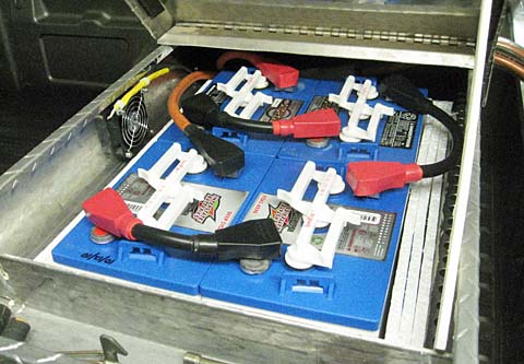
I examined several possible battery arrangements within this box.1. I could put two batteries in each end of the box toward the center, just clearing the gas spring brackets. This would leave about 5 inches of tool storage room at each end, and a large usless area in the center. 2. I could modify the gas spring mounting and place the batteries in the very center of the box. This would leave a lot of room for tools, but would make access to the batteries very hard. 3. I could mount the batteries in the right side of the box and make the lid removeable for easy battery access. This would leave the entire left and center portions of the box available for tools, groceries, etc. I decided on the third option. By mounting the batteries anywhere from as far left as possible to all the way right, the center of gravity of these batteries is only about 12 to 18 inches off center. I like keeping things balanced, but when I drive, my weight is farther off center than the batteries and the two would balance out. I'll determine the exact location of the batteries within this half of the box later.
This is as far as I took this project in 2009. I was not ready to spend the money for the additional batteries, cable, lugs, etc. Over a year later I got serious, ordered all the remaing items and proceeded to complete this addtion of 4 more batteries. September
2010
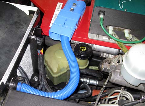
After receiving most of the parts, I disconnected the positive cable from the battery bank under the right front corner of the bed. This cable was the most positive connection to the battery bank and went forward to plug into the controller wiring. I attached lengths of cable to both the vacated battery post and the cable I removed. These were fed through protective plastic tubing and routed up between the back of the cab and the front of the bed. I also routed a power cable for the fan through one of the plastic protectors.
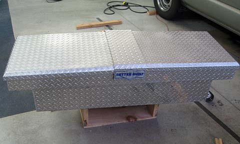
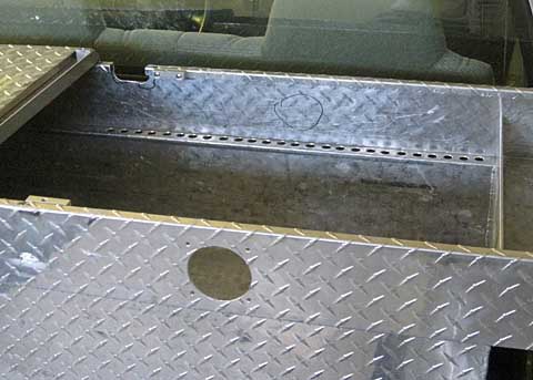
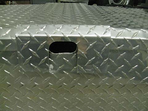
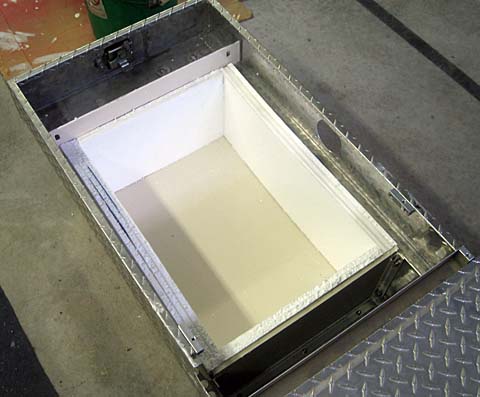
The first new modification I made to the tool box was to bolt it solidly to the truck bed rails. The original mounting was to two plastic blocks which clamped to the bed rail. I did not feel this was adequaate for the heavy batteries. Next I made openings to the center of the front side for the cables to enter the box, a mounting location for the exhaust fan on the rear wall, and air inlet holes.
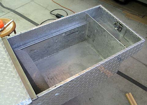
I created a battery box within the tool box by bolting some 1/8 aluminum angles to the front, back, and bottom sides of the box. I lined the bottom of the box and made an end using 3/8 plywood. I painted the interior of the battery box with a heavy coating of latex paint to protect the aluminum. I used 1/2 inch thick styrofoam insulation around the sides of the battery box, using mulitple layers to bring the size down to that of the 4 batteries. I
completed the high current cabeling, terminating in an Anderson type
connector matching the one on the cables feeding the battery box.
I
connected the fan through a smaller Anderson type connector.
I
then routed the fan cable under the truck and up through a bushing
already being used to take several other wires into the cab.
After connecting this wire to the power supply in th meter
box, I
was done with the hardware additions..
Next I adjusted the charging cutoff voltage from 155 to 186 volts, as called for by the battery manufacturer. This was a major advantage to my having spent the extra money to buy the Manzinita charger. It is adjustable for battery banks from 12 volts to over 300 volts. Most of the competing chargers come from the factory set for a specific battery bank voltage. I would have either had to buy a new charger with this change, or if possible at least send the charger back to the manufacturer for a change to the higher voltage. I still need to adjust a couple of the constants in my motor controller to maintain all the inherent safety provisions of the controller. I believe there are no changes needed to my E-meter (battery fuel gage).
First Impressions I drove into town for the first time today (10/20/10) after completing the change to 144 volts. There was no huge increase in performance, but it did seem a little more lively than before. The real test came driving up a long upgrade where I usually fight to keep up to the 40 mph limit, sometimes dropping to 30 mph depending on the state of the traffic and the signals I make or miss. It is the type of grade where if you get slowed down, it is very hard to get back up to speed. Today I was able to easily hold my 40 mph and even accelerate during most of the climb. At the steepest part I just held 40 mph at full throttle. I
also noticed that I can stay in 2nd gear much longer.
Previously,
by the time I reached 30 or 35 mph, the most current I could pull was
about 150 to 200 amps due to the back-EMF of the motor and the limited
input voltage. Now I can pull 300 amps at over 40
mph. OK, it is a couple weeks later and I have driven up the "killer grade"! It is a definite improvement, but the poor truck still struggles. By the top of the 8% grade, I am only slightly faster than before at about 38 or 39 mph. Also, they are about to start construction to place a roundabout (really stupid!) in the middle of the grade. This will be devastating, as I will lose any forward momentum I have attained on the bottom half, and start up the 8% section from about 20 mph! Oh well! Report from Early 2016 I have been driving the truck regularly around town for about 7 years now, with quite satisfying results. The 4 batteries I added in 2010 had a larger effect on range than on performance, and if I were to go back in time knowing what I know now, I would not have expended the time and money to add them. The range and slight performance gains were nice, but the annoyance of having to remove the toolbox with my engine hoist to be able to check or add water to the batteries under the bed was a major pain. The problem of the new roundabout on the "killer grade" was solved when a new road was opened allowing access to that part of town via a much milder grade. After the batteries faded about a year ago, I stopped driving the truck and just ignored the problem. One day recently I decided to take the truck out and see just what the batteries would still do, and in the process one of the batteries in the tool box failed. I had to use the bypass jumper I always carry to get the truck home. I decided that I would remove the toolbox and its associated batteries and go back to a 20 battery system. That is the current status, as I make the decision of whether to make the major investment and convert to lithium batteries (quite expensive), replace the batteries with new lead acid ones, or? Conclusions: I did not accomplish quite everything I set out to do, but I did create a vehicle that fit my usage pattern very satisfactorily for a number of years. Several of the things that I originally planned, but did not complete include: 1. The heater. I purchased a small ceramic heater and disassembled it to obtain the heater element. I bought a couple of high voltage, DC relays to control it, but I never removed the original liquid heater core to install it. I never really missed it. 2. The air conditioning. I went to all the trouble of making a drive for the air conditioning compressor and the power steering pump, and thought by looking at the truck schematics that the AC would work as is. I only tried powering it up once, and for some reason the compressor clutch did not pull in. I never looked further, although it is a simple problem to activate the compressor when the panel switches call for it. It was not too much later when I removed the belt driven power steering pump and replaced it with an electric pump. After that, I never bought a shorter belt for just the AC. It should work fine as I was careful to not disturb any of the freon plumbing and the AC was quite cold before the conversion. 3. Integrated instruments. Originally I had plans to somehow activate the original tachometer with the speed sensor on the motor shaft. As an expediency I bought a normal car after market tachometer which hooked directly to the motor sensor and worked flawlessly. I never pursued connecting the factory tach after that. I was also originally planning to mount the voltmeter and ammeter in the dash, replacing a couple of the original gages. After deciding on the windshield post mounting for these gages, I canceled these plans. In addition I was planning to utilize some of the existing dashboard indicator lamps to perform EV type functions. I never did this. I feel that this has been a very successful project. I spent a lot of time building the truck, and have a great sense of satisfaction for what I accomplished. I spent a lot of money on premium parts and ended up WAY over my budget. The current market value is much less now, although probably not any worse than the normal depreciation on a factory vehicle would have been. I feel I got my money's worth for every dollar I spent! Now it is time to let someone else carry on with this project. I have just listed it for sale and hope I can find a buyer who appreciates it enough to nurture it as I have. Failing to find a suitable buyer, I will disassemble the truck and offer the individual parts for sale so others can create their own dreams. Thanks for having the patience to follow along on my great adventure. I hope you have enjoyed reading about it a fraction as much as I have enjoyed doing it. Dick Final update of 8/26/2016 It's gone! Today I received an offer for my truck, which after a few negotiating adjustments, I accepted. Although we completed the paperwork and the payment portion today, the buyer asked me if I would hold the truck in my garage until he could pick it up. Now, less than a week later, he came with a friend, truck, and borrowed flat bed trailer and picked up the truck and all the parts and pieces I had agreed to give him. About an hour later, off they went with MY (former status) truck.
Bye Bye Truck! Off she goes with a new owner who will care for her and continue to improve her! Postscript The truck is gone and I do miss it, but I do not have to miss driving "electric"! I have since replaced the truck with a 2013 Chevy Volt. With this car I can drive on pure electric power for about 40 miles and recharge it by plugging it in at home (still with free power from my rooftop solar). Any time I exceed the charge in my batteries there is an on board engine/generator which takes over and allows me to continue driving an additional 300 or so miles without any additional effort on my part. Sounds like the perfect car to me! I will publish more on this car shortly. |
||||||||||||||||||||||||||||||||||||||||||||||||||||||||||||||||||||||||||||||||||||||||||||
|
Dick
Mason, Prescott, AZ 7/6/09
|